I do not (yet) understand how voltage multipliers work, but I believe they need an AC input, right? We're dealing with DC here.
yes, it for AC-to-DC. Did not catch that. But you can surely double DC-to-DC too with a suitable driving circuit. I am not very familiar with these tough.
I'd prefer something simpler, smaller, than works directly with 36 VDC
That part of "specs" ruins the whole idea to make a good tube pre with gain and good linearity.
That part of "specs" ruins the whole idea to make a good tube pre with gain and good linearity.
I meant the DC booster should work with 36 VDC input. Of course, the tube stage will want a B+ higher than that, and that's why we need a DC step up converter in the first place.
A couple of math observations that arise when reading this paragraph in Nelson Pass's design document .pdf ... If you prefer to view it in the original document, Search within Acrobat will locate it instantly.
_
_
- "10dB gain" == 3.2X gain
- "3 volts RMS" input signal = ±4.24 volts = 8.5 volts peak-to-trough
- "3 volts RMS" input signal, times a gain of 5X in the front end card, gives 15V RMS output from the front end. That's ±21.2 volts = 42.4 volts peak-to-trough. Don't worry, the Edcor transformer can easily create an output signal that swings beyond the 36V power supply rail. A transformerless front end will have to employ other contrivances.
- 3V RMS input, times an end-to-end gain of 3.2X for the VFET amp as a whole, gives a 9.6V RMS output at the loudspeaker
_
Attachments
Last edited:
Then, with 330K easy load, the 3S4 in triode mode without any cathode follower can do the job. It doesn't come any simpler than this. 3.2x or 5x not really a big deal. With 5x it would need 0.6Vrms at the input which is still a power amp in my book...that can be used as integrated amp with high output sources.
Last edited:
Then, with 330K easy load, the 3S4 in triode mode without any cathode follower can do the job.
The 330k value assumes the capacitance of the SIT/VFET gate is negligible. Is it? I'll try to do a measurement using the SITs I have at hand.
If the reference max power is 8W as pointed out earlier, then with 5x it will need 0.32V rms which is a proper integrated amplifier.
The 330k value assumes the capacitance of the SIT/VFET gate is negligible. Is it? I'll try to do a measurement using the SITs I have at hand.
This normally happens with tubes too. Normally power triodes have Miller capacitance in the 30-100 pF range. If the load stays 10X or better than the tube plate resistance (about 3K for the 3S4 in triode mode), distortion increase respect to higher values of load resistor will be modest. If happening above 20KHz it will be ok, especially because of the modest swing required.
It's a good idea if you check. You could save some money, time and space.
Last edited:
MC34063 with ~100uH and IRF610 should get you there.... I'd prefer something simpler, smaller, than works directly with 36 VDC, and it should be available from a proper electronics seller like Mouser, Digi Key, etc.
Last edited:
If the reference max power is 8W as pointed out earlier, then with 5x it will need 0.32V rms which is a proper integrated amplifier.
I am confused.
Can we agree that we want to replace the base preamp (with edcor tranformer) with a tube preamp?
This would mean that we need a pre with 7.5x voltage gain (we would want 15Vrms for 2Vrms input)
Preferably at 0.1% distortion
and capable to do that into maybe 5kOhm?
Is this feasable with B+ of 75V only?
"Is this feasable with B+ of 75V only?"
I would say no.
15 Vrms is 42 Vpp. There is not enough headroom for any tube to work linearly, especially if the load is 5 kohms.
I would say no.
15 Vrms is 42 Vpp. There is not enough headroom for any tube to work linearly, especially if the load is 5 kohms.
A couple of math observations that arise when reading this paragraph in Nelson Pass's design document...
I read this article at least five times. It seems this was not enough. I missed the part that says that the follower output stage as voltage gain substantially lower than 1. This means the input/driver stage would benefit from a bit more gain than what I thought initially.
Can we agree that we want to replace the base preamp (with edcor tranformer) with a tube preamp?
This would mean that we need a pre with 7.5x voltage gain
Yes. I adjusted the design targets in the first post with the new voltage gain value.
MC34063 with ~100uH and IRF610 should get you there.
I have zero experience with DC converter stuff. Could you show a circuit or example? Would it be possible to design a smallish board containing both the DC converter and the audio circuit?
Since this thread is appearing in the Tubes / Valves forum and not the Pass Labs forum, some extra background information is probably necessary. Here is a copy of the DIY Sony VFET part1 document that Nelson Pass provided with his introduction of the amp.
Note that the input resistance of the output stage is over 100k Ohms, and the gain of this stage is less than unity. That suggests that a good target for the gain of the vacuum tube input stage would be from 17db to 20db, depending on the output capability of the preamp one is using to drive this amplifier.
Also note that the VFET amp as being delivered to most of the builders is designed to work with an external 36V SMPS brick power supply. There is no AC voltage present inside the chassis, nor is there much room to build a separate linear PSU. There are pictures of the inside of the amp here: DIY Sony VFET Builders thread
Attachments
...common cathode + cathode follower...
That was one of my fist thots, CCS at the top of the CC and the bottom of the CF improve things considerably.
dave
6N6P
That was one of the tubes i was thinking could be used. Really beefy, sometimes used as a small spud amp by itself.
dave
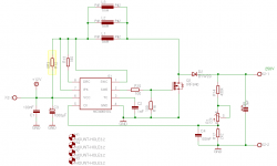
Get both ST datasheet mc34063ab.pdf and On Semi mc34063a-d.pdf.Could you show a circuit or example?
Set frequency using Ct and max switching current using Rsc. Output voltage is determined by 1.25V*R2/R1. But you need an external switching device such as an IRF610 to allow output voltage > 40V as shown in the last example on ST datasheet. Attached is a schematic I saw from Probleme mit MC34063 step up - Mikrocontroller.net as an example but you need to determine appropriate values for Ct, Rsc, L1, feedback resistors R1 and R2 for your specific need.
Sure.Would it be possible to design a smallish board containing both the DC converter and the audio circuit?
Attachments
Any idea of the input capacitance of the 2SJ28 wired as a follower?
How about a low mu triode loaded by a gyrator / hybrid mu-follower, à la Ale Moglia's 01A preamp? Low distortion, low output impedance buffered by the lower gyrator device, JFET in Ale's case.
01a Preamp (Gen2) – Bartola(R) Valves
Could also use a cascode CCS load and take the output off the source of the lower device, a simpler approach, although some say the sound of the gyrator is better. Many other tubes can be substituted for the 01A, 26 perhaps, or maybe a linear IDHT for simplicity, like the 37.
Lots of ways to go about it. Could also use a pair of dual triodes like the 6BX7, mu of 10. Load one section however you like and use the other as a cathode follower.
Just throwing out some ideas 🙂
I am confused.
Can we agree that we want to replace the base preamp (with edcor tranformer) with a tube preamp?
This would mean that we need a pre with 7.5x voltage gain (we would want 15Vrms for 2Vrms input)
Preferably at 0.1% distortion
and capable to do that into maybe 5kOhm?
Is this feasable with B+ of 75V only?
These are totally different numbers respect to those we started from and if you add also compact size a acceptable cost then I think the answer is nope.
I have no idea of the original design. I did some estimates on the numbers I was given at the beginning. If someone could point me to the actual design/article I will read it happily. Always good stuff from Pass....
Gain with tubes is not a problem....there is a wide choice. You have 2 ways:
1) you either pick a linear device (generally a direct heated triode or direct heated pentode in triode mode but there are few exceptions)
2) use a convenient device where you apply some type local feedback to get low distortion and the desired gain. The second solution might be less appealing but properly done it works nicely too, IMHO....
With 75V only, 15Vrms @0.1% THD into an optimised load...maybe it's possible. This means that you will need a source follower driving the actual 5K load. A cathode follower might be possible with some high gm tube but really not worth the trouble as this should be transparent.....
It needs some experiments because this is uncommon. Normally the use of lower voltage with tubes correlates with much lower demand.
I think the small miniature tubes are the only viable choice, also taking into account cost and size. If you can use more plate voltage, at least 130-150V things change a lot and the choice is a lot wider....
Another miniature directly heated pentode like the 3S4 with 30-35% more gain (this is my estimate...) is the 3V4. I have no triode connection data but the tube is from the same family with higher mutual conductance and delivers the same power with less distortion in pentode mode. Same filament requirements but better used at 85-90V as recommended in the datasheet if you are looking for 15 Vrms output at low distortion.
Or better, at least you should consider experiment with 90V on the bench and then see if you can go down to 75V.
Last edited:
- Home
- Amplifiers
- Tubes / Valves
- Designing a vacuum tube front end card for the VFET DIY amp