I looked at the MeanWell DC boosters. There are some options with a 48 VDC output that could be "stacked" onto the existing 36 VDC. However, non of these converters will take 36 VDC as input.
If we use a second external brick to produce the B+ for the tubes then we can use one that produces what we want (100V or more)
(The tube company BTB Elektronik makes several amps that use bricks for B+)
For the heaters the easiest is to use what we already have, the 36V for the VFET.
The tubes EF860 and IL861 are excellent performers and their heaters will just be happy when put in series (The unusual heater voltage makes also for a very low price of these tubes)
SMPS for tube circuit
Had a look at the datasheet of the chip used by Pete Millet for the hvflyback converter. Max input voltage is 60V.
Therefore we could maybe put it inside the VFET. The pcb is small, some 5 x 8 cm...
Had a look at the datasheet of the chip used by Pete Millet for the hvflyback converter. Max input voltage is 60V.
Therefore we could maybe put it inside the VFET. The pcb is small, some 5 x 8 cm...
I think now would be a good time for you to start a brand new thread called "Help me design a vacuum tube front end card for the VFET DIY amp". Then we can ask the Forum moderators to move over the vacuum tube inquiry posts.
I also think you should choose a new name for your vacuum tube front end card, a name which isn't any of Scourge, Bulwark, Marauder, or Dreadnought.
I also think you should choose a new name for your vacuum tube front end card, a name which isn't any of Scourge, Bulwark, Marauder, or Dreadnought.
This thread is about designing a vacuum tube front end for the VFET DIY amp. There are already a number of sand based front ends, but I thought a vacuum option would be nice, too!
Design targets:
(This post is a followup to the discussion that started in the "Scourge, Bulwark, Marauder, Dreadnought front end cards for DIY VFET amp" thread, and relevant posts from this thread will be moved here.)
Design targets:
- Should be relatively easy to build so the average DIY VFET builder can cope with it.
- Should fit in the DIY VFET chassis. If possible, the chassis should not need any modifications (like drilling more holes).
- Avoid dangerously high voltages -- this is for rookies!
- The front end needs to provide high input impedance and low output impedance to drive the VFET/SIT output stage.
- Single ended input signals with up to ±2 Vpeak (4 V peak-to-peak).
- Voltage gain of approximately 5.
(This post is a followup to the discussion that started in the "Scourge, Bulwark, Marauder, Dreadnought front end cards for DIY VFET amp" thread, and relevant posts from this thread will be moved here.)
Last edited:
What level of sweetness is desired?
Is it for people detected of mild/mid/high diabetic,
for general/normal/ average taste people,
or people with extreme sweet taste addiction😀
Is it for people detected of mild/mid/high diabetic,
for general/normal/ average taste people,
or people with extreme sweet taste addiction😀
Not sure what you mean... I'd say to keep it simple, and let's try to avoid too much exotica and rare tubes. A simple triode gain stage, possibly with a CCS load and a "power drive" follower for low output impedance is all it takes, if you ask me. But other ideas and suggestions are welcome!
The goal is to make a simple, reliable, fool-proof design that performs well. I don't care if the tube of choice ends up as a good old but "boring" 6DJ8, if that's what it takes.
The thing is that the VFET DIY amp runs off an external 36 VDC brick (see link in the first post). This makes things easier and safer for novices, because it avoids working with mains power. There are some low-voltage tubes around that might work with such low B+, but I am not sure these would make for a good input stage. There have been some ideas to use step-up converters to obtain higher DC from the 36 VDC inside the amp chassis. Another idea was to add an external power supply (possibly some 48 VDC bricks in series) for a separate B+ supply. The wirking/connections needed for this might be feasible via the 4-pin power supply connector that is already available with the VFET chassis, but would mean that there is some highish DC voltage outside the chassis. I don't know where a sane DC voltage limit should be in order to make things safe for novices.
Similar thoughts on the filament supply... while there may be some tubes that would work with 36 VDC as filament supply (filaments in series), it might be easier to use a step-down converter for the filament supply.
The trick would be to find suitable DC converters that will run off a 36 VDC input.
This thread is about designing a vacuum tube front end for the VFET DIY amp. There are already a number of sand based front ends, but I thought a vacuum option would be nice, too!
Design targets:
- Should be relatively easy to build so the average DIY VFET builder can cope with it.
- Should fit in the DIY VFET chassis. If possible, the chassis should not need any modifications (like drilling more holes).
- Avoid dangerously high voltages -- this is for rookies!
- The front end needs to provide high input impedance and low output impedance to drive the VFET/SIT output stage.
- Single ended input signals with up to ±2 Vpeak (4 V peak-to-peak).
- Voltage gain of approximately 5.
(This post is a followup to the discussion that started in the "Scourge, Bulwark, Marauder, Dreadnought front end cards for DIY VFET amp" thread, and relevant posts from this thread will be moved here.)
Unless you use feedback or step-down transformer coupling to VFET (which would also give low Zout) the only viable way I can think of right now is to use directly heated low mu triodes DC-coupled to a follower.
A low gain triode does not need to be an old one. More recent miniature devices with low power consumption can do the job as well. I am thinking of the 3S4 miniature directly heated pentode, for example:
1) This works with 1.4 VA (1.4V/100mA) filament and low plate voltage (90V max). The filament heating must be DC to avoid hum at the very least. A lot better if use both voltage and current reg. The current reg main goal is to give a very high impedance path towards supply and eliminate any form of measurable IMD with the supply itself. There are several other types of this little DHP that can be used.
2) A triode connected 3S4 is a good linear device and it's mu is...5! If use a simple cascode CCS as anode load (made of 2 depletion mode MOSFETS +2 resistors in total) the actual gain will be very close to 5. Here is a datasheet with average triode curves:
https://frank.pocnet.net/sheets/127/3/3S4.pdf
As it was common practice these are average curves (i.e. averaged over lots of devices). Individual devices will have +/-20% variance on mutual conductance and plate resistance but gain will be fairly constant and linearity will be better. Example of operating point could be: 75V plate voltage and 5-6 mA current and the bias will be -10V...so it will have an overload capability of +/- 8V at the very least.....of course there is lots of flexibility there. I would expect that the area at lower voltage and higher current will be more linear. So one can play around there to get the required specs and best linearity at the same time.
3) the 3S2 is still pretty common and it's price is reasonable. To all those people who are going to use this: Please don't make it too expensive buying everything you see and speculating. This is hopeless because there are so many similar types that can be used in its place....including several sub-miniature types.
Last edited:
Interesting the 3S4 tube
Agree with the idea of DC coupling and follower (mosfet follower perfectly ok with me)
Low gain of 5 ? Well Pa said that you need 3Vrms to reach full output...
If you have a "lowish" source i think i would not be happy with a gain of 5.
What we also need to look at is how much voltage swing we get with what distortion pattern.
The VFET itself has enough distortion. I do not want to add a lot
Interesting the 3S4 tube
In tube world, speaking of tubes intrinsic mu: 1-20 is low gain, 20-40 is medium gain, 40-100 (even more with some pentodes) is high gain.
3 Vrms output you can could expect THD in the 0.1% area with 2nd harmonic (very) dominant if use CCS load with directly heated (pseudo)triodes. The most linear ones, that are true triodes but unfortunately are not compact, can do 0.02-0.03%....
A variant for the plate load (which I generally prefer) would be a gyrator but it's a bit more complicated. Some gyrators mini-boards are available from members of this forum....
Last edited:
Is inverting amplifier topology ok? (voltage amplifier + follower)
Or should it be non inverting a I see as good design principle?
Or should it be non inverting a I see as good design principle?
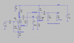
Another way to get it done is in the picture: common cathode + bootstrapped cathode follower. Gain of 4 and THD at 0.03% for 10 Vrms output driving 50K even with a modest ECC82/12AU7. But there is some feedback (which is not the evil if properly used, IMHO).
More details at this page (section 8): Preamps
More details at this page (section 8): Preamps
Attachments
Low gain of 5 ? Well Pa said that you need 3Vrms to reach full output...
If you have a "lowish" source i think i would not be happy with a gain of 5.
The THD plot of the VFET rises to 1% at 5 W into 8 Ohm, and stops at 10 W. I'd say the amp is good for about 8 W into 8 Ohm. That's 8 Vrms output, or 11.2 Vpk. Since the VFET output stage is a voltage follower, the input/driver stage also needs to swing 11.2 Vpk. With a 2 Vpk input signal, the gain required 11.2/2 = 5.6, not far off the value I gave in the first post.
I agree that the input/driver stage should not add a lot of harmonic distortion on top of that from the VFET output stage. This could be achieved with a bit of feedback using a tube that has a mu higher than 5.
That said, I do like the 3S4 tube as a triode, as it will work well with a lowish B+ and can be biased at a grid voltage well below -2 V, so even a full 2 Vpk input signal will get it close to grid current. A simple "current source" for the heater supply could be achieved by running the 1.4 V filaments via a dropping resistor from the 36 V PSU. It would be cool if the B+ (75V or slightly more to allow for the CCS drop) could be derived from the 36 VDC, too. Is anyone aware of a simple step-up converter that would allow us to do that?
EDIT: regarding harmonic distortion: if we are lucky (or clever), the driver distortion would be opposite phase than that of the output stage, so we'd get less overall distortion.
Last edited:
You can multiply the voltage (at expense of current which is low in this case).It would be cool if the B+ (75V or slightly more to allow for the CCS drop) could be derived from the 36 VDC, too. Is anyone aware of a simple step-up converter that would allow us to do that?
https://www.electronics-tutorials.ws/blog/voltage-multiplier-circuit.html
You can use DC-DC 8~32V to 45~390V High Voltage Boost Converter but need to reduce 4V using IRF cap multiplier or the likes for 36V SMPS supply.

Is inverting amplifier topology ok? (voltage amplifier + follower)
Or should it be non inverting a I see as good design principle?
As far as I can tell, the VFET output stage is inverting as well, the idea is to reverse the polarit of the speaker cables to get the polarity right. I don't think it would be wrong to have an inverting input stage.
Another way to get it done is in the picture: common cathode + bootstrapped cathode follower. Gain of 4 and THD at 0.03% for 10 Vrms output driving 50K even with a modest ECC82/12AU7. But there is some feedback (which is not the evil if properly used, IMHO).
More details at this page (section 8): Preamps
Why not.
You can multiply the voltage (at expense of current which is low in this case).
https://www.electronics-tutorials.ws/blog/voltage-multiplier-circuit.html
I do not (yet) understand how voltage multipliers work, but I believe they need an AC input, right? We're dealing with DC here.
You can use DC-DC 8~32V to 45~390V High Voltage Boost Converter but need to reduce 4V using IRF cap multiplier or the likes for 36V SMPS supply.
I'd prefer something simpler, smaller, than works directly with 36 VDC, and it should be available from a proper electronics seller like Mouser, Digi Key, etc. No China sellers at ebay! Meanwell has some standalone modules that could go on a PCB, but I haven't found one that will work with 36 VDC input.
Last edited:
- Home
- Amplifiers
- Tubes / Valves
- Designing a vacuum tube front end card for the VFET DIY amp