Would anybody like to answer these questions from a diyAudio member? I received them in a Private Message but I think 250,000 heads are better than one, and the community has a lot more collective wisdom than any one person.
I have a quick question on snubbers
I want to apply an RC snubber parallel to the transformer secondary in a tube appliance. The secondary voltage is 240VAC. My plan is to experiment with a 100nF capacitor and a series 10R resistor as an initial value, then changing the resistor to find the optimal value. On the long term I might build a Qasimodo test rig.
Is it a good practice to observe the ringing waveform on the snubber resistor, using a floating battery powered oscilloscope? Tektronix 214 with 500kHz BW. I am afraid I will not be able to measure across the transformer secondary with this scope, because it might exceed its voltage limit. But on the resistor there is ringing HF current that drops relatively low voltage, easier to measure. And the mains voltage won't interfere.
Also is it OK to connect 10nF capacitors parallel to each diode in the bridge? As I understand the effect is to reduce the ringing frequency, so that the RC snubber will dampen it more easily. Is that a good practice?
Make a quick survey of the Results Only thread -- you'll probably find someone reporting on a circuit that is close enough to your situation to borrow those as starter values.
No. One of QuasiModo's best points is to keep you, and your oscilloscope, a safe distance from such horrors as 339Vp-p energy.
It is certainly commonly done! 😉 There is nothing to be gained by *reducing the ringing frequency*. The damping you can achieve (if you build and apply QuasiModo) can be *mathmatically perfect* -- and can be completed at less than 15 volts.
Build it, or don't, but is sounds to me (likely bottom 10-percentile of the 250,000) like you've already applied more thought to the issue, than it would have taken to build this clever little bit of kit! 😀 And you can use it again and again!
Cheers
edit: Thanks for letting us 'help out', MJ. Sorry I lack your grace, patience, and good humor.
Last edited:
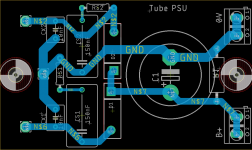
I have a draft for a PCB to hold the snubbers, rectifier diodes and 220uF main filter cap.
It would be great if someone can double-check that the layout is correct, along with any other improvements or suggestions to the layout.
The mounting holes and PCB size are intentional, to fit on top of the power transformer mounting tabs.
edit: also wanted to mention the rectifier diodes I chose are TO-247 soft-recovery ISL9R30120G2 (Mark's "belt and suspenders" approach).
I assume that at 30A rating, they won't need heatsinking for the 100mA B+.
Rick, Mark,
As you two seem to be most active here lately, any glaring issues with that PCB layout?
Are the snubbers laid out correctly with regards to the Center-Tap (which ties to the capacitor neg pin). ?
Any recommendations to make that look cleaner, I'm not sure happy with it.
Thanks
Last edited:
I think you want all three wires of the transformer secondary, to solder directly onto your snubber-and-rectifier board. You want the snubbers to be as physically close to the transformer as possible, and that includes short wires, and that includes a short center tap wire.
It certainly has a lovely symmetry.
I once got scolded for top-side foil to a flush-mounted part. Plus, since it's the ONLY top side foil, I'd look for a way to eliminate it. Either using a jumper (it's no sin -- some amazingly complex boards have come from Japan, for example, with scads of jumpers -- single sided foil), or moving the lower rectifier so that it straddles the ground trace.
By the way, where is the connection for the transformer center tap?
Otherwise, it looks correct electrically.
Cheers
Thanks Mark and Rick.
In the previous layout, the transformer CT was intended to connect to the 0V terminal at the output of the filter cap.
Here is a new version, it seems better to me but I can count the number of PCB's I've "designed" on one hand so would definitely appreciate another opinion.
All the transformer wires now connect to the left side and all traces are on the bottom side.
Due to room constraints, the bleeder resistor is mounted on the opposite side of the board.
Attachments
The way you have it looks OK to me. Are you sure the body of the bleeder resistor has clearance on the transformer frame?
I did a little mark-up, in case you haven't already sent off the Gerbers. The performance improvement would be tiny -- likely unmeasurable. But there is a small advantage in serviceability. Yours is fine, though.
Cheers
I did a little mark-up, in case you haven't already sent off the Gerbers. The performance improvement would be tiny -- likely unmeasurable. But there is a small advantage in serviceability. Yours is fine, though.
Cheers
Attachments
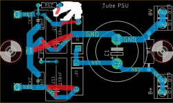
The resistor shouldn't be a problem, that PCB sits on two 19.05mm standoffs (for clearance of the wires).
I have not sent them yet, so can definitely make any improvements if needed.
Can you please explain the reasoning behind the change? My EE knowledge is very limited.
I routed it like that because I thought it was a similar case when laying a CRC PS filter. e.g, you want the trace to exit the last cap (and not through the resistor pad), to ensure that no frequencies bypass the cap and go directly from the resistor.
The charging pulses through the rectifiers are the big ones. They deserve the heaviest, most-direct traces.
The current pulses through the snubber networks, though higher frequency, have the advantage of a path already containing resistance to provide damping.
Providing little offshoots of a heavy path improves solderabilty. Plus, in a pinch, a tech can score the offshoot to disconnect that part, without impeding the rest of the circuit's function.
Regards
Last edited:
My Quasimodo is running now, too...
But there is one question : yesterday measured a toroid with 2x18V secondarys...
Shorting the primay winding doesn´t change anything.
Could this be ? Or is there a defect ?
But there is one question : yesterday measured a toroid with 2x18V secondarys...
Shorting the primay winding doesn´t change anything.
Could this be ? Or is there a defect ?
Something Quasimodo snubbing does that I haven't seen commented on is transformer mechanical noise is reduced/eliminated. Some transformers are noisier than others (winding tightness, vacuum or epoxy impregnation, circuit values, etc). As you progressively snub your high and low level components you can notice the reduction in the audible transformer low level harmonics/buzzing for each snubbed component, in addition to the improved electrical noise floor of the power supply/audio circuit.
yes I've seen that shorting some windings for testing doesn't change the snubbing results, but I'm sure its best to short all of them as Marc instructed.
yes I've seen that shorting some windings for testing doesn't change the snubbing results, but I'm sure its best to short all of them as Marc instructed.
Last edited:
It's strongly recommended "best lab practice" to short all other transformer windings, every time you perform a Quasimodo test. You don't know how this new transformer is going to behave -- and if you did know, you wouldn't need a Quasimodo. High voltage vacuum tube transformers are different than low voltage solid state transformers. Toroids are different than E-I core, and so forth. Don't cut corners on good lab procedure based on one lucky experience with one transformer.
Hello everyone, sorry if it was already. Does anyone have a list of links for buying the necessary components in the moser? Or maybe part numbers of part numbers? Thank you)
If you want... I have a few completed and tested units in the closet...Hello everyone, sorry if it was already. Does anyone have a list of links for buying the necessary components in the moser? Or maybe part numbers of part numbers? Thank you)
Post 1 has everything.
Since I may be wrong, here it is...
Thank you for the archive, but how can I open files in it? I have windows. And on the first page I didn't find it. exactly a table with part numbers
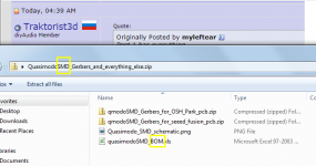
Download the "everything" .zip archive of the board you are interested in. "V3" is surface mount and "V4" is thru hole. Both are attached to post #1 of this Forum thread.
Save the .zip archive on your computer (not yet in the cloud).
Open the .zip archive. For V3 you will see the same thing as Figure 1 below.
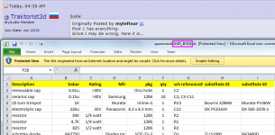
Find the Bill Of Materials (abbreviated "BOM"). It is a Microsoft Excel spreadsheet and for me, on Windows it opens just fine.
You will see the same thing as Figure 2 below.
_
Save the .zip archive on your computer (not yet in the cloud).
Open the .zip archive. For V3 you will see the same thing as Figure 1 below.
Find the Bill Of Materials (abbreviated "BOM"). It is a Microsoft Excel spreadsheet and for me, on Windows it opens just fine.
You will see the same thing as Figure 2 below.
_
Attachments
Hey Mark, I checked the results thread and didn’t find anything but do you know if there have been snubber values determined for the Antek 0522?
If it's not in Quasimodo Results (ONLY), I have no idea whether it is or is not mentioned elsewhere. Maybe you can hire a middle schooler, age 12-14, to search this thread (Quasimodo general chitchat) for posts which contain the keywords you supply. Kids that age are full of energy and usually are thrilled to work for Real Money.
- Home
- Amplifiers
- Power Supplies
- Simple, no-math transformer snubber using Quasimodo test-jig