Hi Kuro
there is no kit. You have to source everything yourself... Mark kindly provided us with everything needed, like the files to be sent to the PCBs-factory, the bom and the documentations... Sometimes one of the builders ordered a dozen or so boards to get a lower price per unit, surplus is then often given away for a "good price" (sometimes even free). Ask around...
there is no kit. You have to source everything yourself... Mark kindly provided us with everything needed, like the files to be sent to the PCBs-factory, the bom and the documentations... Sometimes one of the builders ordered a dozen or so boards to get a lower price per unit, surplus is then often given away for a "good price" (sometimes even free). Ask around...
Hello,
I dont want to start a new thread and i think someone here will know the answer.
I need to buy a split bobbin transformer for a friend. One similar to the one in the attachment. These all have double secondary windings.
Suppose i need 20 volt 2A . I know i can make it two ways.
2 20 volt 1A in parallel or 2 10volt 2A in series both will give 20 volt 2A.
Is there any reason i should prefer one over the other?
Greetings, eduard
Attachments
Hello Eduard, for the transformer you posted Triad FP20-300, it is only rated 6VA, it can provide 20.0VCT @ 0.300Amps using the secondary in series, but is .3A enough for your requirements or do you really need 2 Amps? Do you need a center tap, that would be 10-0-10.When using the secondary in parallel it can only provide 10.0V @ 0.600Amps not 20V and also .6 Amp doesn't meet your 2Amp need. If you require 20V and 2 Amps, you need a transformer rated for 40VA minimum, so look at the next standard range up, a 48 VA rated transformer. A Triad FP20-2400 is 48VA and with secondaries in series yields 20.0V CT at 2.4 A. Or a Triad FP40-1200 is 48VA and with secondaries in parallel yields 20.0V at 2.4 A. Clarify what Amperage your circuit requires and choose a transformer with an appropriate VA rating, and also determine if your circuit needs a center tap for series, or no center tap then parallel secondary.
PC Mount Flat Pack™ Power Transformers On Triad Magnetics
PC Mount Flat Pack™ Power Transformers On Triad Magnetics
Does anyone have the calculated snubber values for an Antek 400VA 18V (AS-4218 - 400VA 18V) transformer?
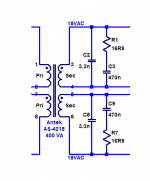
However, in pdf about Quasimodo Mark wrote: "Cs should be larger than Cx {the final paragraph of Appendix A explains why}, and in my own audio work I usually select Cs to be about 15X greater than Cx. When fitting a snubber to existing equipment that already has a Cx installed, I would of course install that same value of Cx into the Quasimodo test jig, and also install a Cs which is 10X or 20X larger.
Thank you for this thread and the information, very clear and understandable.
Thusly emboldened, I probed a few dual rail power supplies I have knocked together over the last year or so and found ringing on the rectifier pulses on most, but not all.
Something strange I noticed was that for a small centre tapped dual rail supply, fitting a snubber (10nf, 100nf, 470r ) on only one rail also damped out the rectifier ringing on the other rail.
Standard design with a bridge rectifier, CRC with 4400uf-5R-4400uf
Is that a quirk of centre tapped vs dual secondary?
Did you perhaps, fit a single Cx, Cs, R snubber across the entire secondary, instead of 1-each, center-tap-to-rectifier node?
If not, I think that could be due to some nominal amount of coupling between the leakage inductances of the two transformer windings. Could be quite a bit if it's bi-filar wound. Of course, that would be unusual for a power transformer.
Cheers
If not, I think that could be due to some nominal amount of coupling between the leakage inductances of the two transformer windings. Could be quite a bit if it's bi-filar wound. Of course, that would be unusual for a power transformer.
Cheers
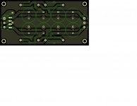
I’m pretty sure it’s across the centre tap ( bottom of the three left hand most connections on the PCB) and a winding as per the photos.
The ringing shows up under load with none apparent at idle. I didn't build a jig as per the OP, rather soldered the caps and a small trim pot directly to the pcb and twiddled about with it until the ringing looked to be damped out on the osciliscope.
The intention was to then simply put another set of caps and the same resistor value from the centre tap to the other winding PCB connection but on probing, it didn't appear to need it?!
I took the snubber off and probed that same winding connection again and found that the ringing returned and so I'm thinking it's not my bad probing technique.
Thanks for your help. 🙂
Attachments

Last edited:
I’m wondering if this same idea, of a C and RC together, would be of benefit if used on the mains side, or even in a separate enclosure and plugged into the mains?
I am thinking this could be used for equipment that is still under warranty, or is too expensive to modify and it would affect the re-sale value. Using a C & RC on the mains to lower/reduce the unwanted energy on the mains wiring. This could be built into an electrical box with a cord on it and plugged in next to a noisy piece of equipment. I have read that Romex wire has an impedance of around 120 ohms, we could us that a starting point for the RC design.
Just an idea.
Rick, try the experiment and see whether you like the results! You'll want to perform your first proof-of-concept tests using a specially chosen ensemble of transformer + rectifiers + bulk filter capacitors + load current. That ensemble would be: whichever setup gives the biggest nastiest oscillatory ringing on the secondary, as viewed with an AC coupled scope probe. Now the "Before" picture is quite dramatic, and you'll have an easier time comparing the "After" picture against the "Before".
However I have a nagging feeling that putting anything in parallel with the transformer primary, won't do much good for diode-excited RLC oscillation on the transformer secondary. The primary is already a super low impedance circuit, thanks to the AC mains, and I suspect that connecting a C+RC snubbing network in parallel with this super low impedance, won't do much. Including: won't provide much damping to the secondary.
But that's just opinion. Lab measured data is FACT which beats opinion every time.
MJ
Looks to be right, just the way you described it, Flashheart.
One thing to keep in mind about testing one side, then just duplicating that on the other winding: Depending on how the transformer is wound, the duplicated snubber may be less than optimum. It may not be off far enough for you to object, but might be worth at least checking. Remember it's the leakage inductance that we're trying to dampen.
Regards
Last edited:
I got a curious question to you all: can you hear the difference in sound after adding a snubber?
I've the kit now (still waiting to be soldered out). I'd like to add snubbers to all the linear power supplies in my setup. That's actually quite a few to add (6 LPS).
I've the kit now (still waiting to be soldered out). I'd like to add snubbers to all the linear power supplies in my setup. That's actually quite a few to add (6 LPS).
diyAudio members have posted before-and-after listening reviews in this thread, from time to time. Some reported that they hear no difference, others reported that they heard significant differences and the with-snubber version ("After") was greatly preferred.
Some combinations of (transformer + diodes + capacitors + load current) have enough HF loss (self-damping) that they don't ring. Adding components to eliminate ringing, probably doesn't help very much. Other combinations ring like a banshee and eliminating this is probably helpful.
I hold the opinion that the anti-ringing snubber components are dirt cheap to add so WHY NOT install them every time? Others feel differently. Some feel strongly about it. 🙂
I just got my Quasimodo V4 up and running. I just used it to find the resistor value for my R-core transformer. And I found the resistor value to be around 10 ohm.
Would such low value be a problem since it is essentially across the transformer's secondary, wouldn't it be dissipating huge amount of power?
Would such low value be a problem since it is essentially across the transformer's secondary, wouldn't it be dissipating huge amount of power?
- Home
- Amplifiers
- Power Supplies
- Simple, no-math transformer snubber using Quasimodo test-jig