In the seven and a half years since Quasimodo was released, there have been several Forum postings in this thread, discussing before-Quasimodo versus after-Quasimodo listening impressions and reviews. I estimate that there have been somewhere between five and ten such postings, here on this thread, since September 2013. Who were the authors of these messages? Sorry, don't remember. When were the posts made? Sorry, don't remember. How can somebody easily find these posts with little effort? Sorry, don't know.
Wave interpretation - video - RIGOL DS1054Z
Hi,
I‘ve recorded a video
Quasimodo V4 Snubber - YouTube
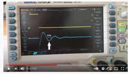
of the measure of an AUDIOPHONICS transformer with 2 x 115 V primary and 2 x 9 V secondary, 30 VA. The video starts with RS = 2.5 ohms and ends with 33.8 ohms. First half of the sine wave increases at the end of the video. Please give me an advice if I do everything right and what’s the optimum point I should use for taking resistors measurement.
Thanks a lot. Ronny
Hi,
I‘ve recorded a video
Quasimodo V4 Snubber - YouTube
of the measure of an AUDIOPHONICS transformer with 2 x 115 V primary and 2 x 9 V secondary, 30 VA. The video starts with RS = 2.5 ohms and ends with 33.8 ohms. First half of the sine wave increases at the end of the video. Please give me an advice if I do everything right and what’s the optimum point I should use for taking resistors measurement.
Thanks a lot. Ronny
Good idea to take a video, Ronny. Unfortunately the potentiometer made a "hiccup" right at the crucial moment, namely the video timestamp 0:10.
What you want to do is smoooooothly and sloooooowly turn the pot while watching the bump-down on the oscilloscope. See arrow on attached image. You want to slooooowly reduce that bump-down until it juuuuuuust goes flatline. Until it hits the goal I've marked in the photo.
Ten-turn and twenty-turn trimmer potentiometers don't usually hiccup that way; maybe you can unplug your trimpot from the board and slap it down on the tabletop to jostle it back into alignment. Or even try a different trimmer. If your optimum reading is something like 60 ohms, you can use a 100 ohm trimmer (for example) and get super fine granularity.
MJ
_
Attachments
Hi Mark,
thank You so much for answering me. I want to tell You that unfortunately I‘ve soldered the MCP1407 the first time in wrong direction (marking!), but I don’t have driven the unit that way. I think it’s important to tell You the complete story 😉 Hope this has no impact 😱 Currently my properly filled electronics part box
doesn’t contain low value potentiometers. I’ll order some of them or try to connect some resistors parallel or in series to get the flatten curve. Kind regards from Grafenau (Wurttemberg) Ronny
Ronny, a 1K trimmer will work fine, you don't need smaller resistances. But if you're ordering parts anyway, I recommend spending a few additional Euro and buy a 200R trimmer and a 100R trimmer in addition to your second 1K trimmer. The smaller resistance trimmers merely give you finer grained control near the optimum.
Hi Mark,
I‘ll follow Your advice. What do You thinking after watching the video. Could it be that the MCP1407 was overheated during unsoldering, new positioning and re-soldering because of my former fault? Maybe it’s difficult to answer but I‘m sure if someone knows than You 😉 There is probably a chance to test if that this part is still working properly.
I‘ll follow Your advice. What do You thinking after watching the video. Could it be that the MCP1407 was overheated during unsoldering, new positioning and re-soldering because of my former fault? Maybe it’s difficult to answer but I‘m sure if someone knows than You 😉 There is probably a chance to test if that this part is still working properly.
Hi Mark,
I guess I‘ve reached my goal: 24.5 Ohms for ZEROZONE (personalized) R-Core Transformer primary 230V, secondary 15V 3A

Thank You very much for all Your support.
Ronny
I guess I‘ve reached my goal: 24.5 Ohms for ZEROZONE (personalized) R-Core Transformer primary 230V, secondary 15V 3A

Thank You very much for all Your support.
Ronny
I had an enjoyable time checking what CRC snubber would suit a tube amplifier power supply using a power transformer with 400-0-400V 180mA secondary and ss diodes for full-wave rectification. Results are in post #110 in results only thread.
An issue is that C parts need to be rated for circa 1kVdc and 400Vacrms, so practicality can push component choice to low capacitance values when wanting to deploy a snubber for valve amp B+ supplies.
To assist in confirming winding inductance and capacitance, and the waveform resonance frequency on a scope, I made an impedance plot of each 400V half-winding, both for all other windings open, and for closed. I can recommend using a soundcard and REW software for that type of frequency sweep as its automated and the plot can interrogate what inductance or capacitance is measured at any frequency.
The winding capacitance was about 600pF, and leakage inductance about 6.1mH, so using Cx=1nF gave caps that I had, and made the resonant frequency about 50kHz - so not too low, or high. Similarly I have 10nF with suitable voltage rating for Cs. I also have 470pF and 4n7 caps and they gave a similar scope result.
I am going to try and measure the rectification transient using the soundcard and REW spectrum plot, by playing around with the snubber values and diode type and supply loading. I'm hoping the soundcard can identify any resonance so need to keep it suitably below the 96kHz measurement bandwidth. The supply is also close to choke input style, so the diodes have a much harder time at commutation. The soundcard should give me much better discrimination than a scope.
Last edited:
One of the reasons why the Quasimodo test jig was created in the first place, was that the leakage inductance of power transformers is not constant! It varies with frequency. At least, it did on all of the power transformers that I measured myself in 2013. Sorry to shout but this turned out to be a long post and I don't want the main message to get lost in an intimidating wall of text.
When leakage inductance varies, it creates a problem: to design an effective snubber, you need to know the inductance and the capacitance of the parallel resonant circuit. Once those are in hand, you simply apply conventional 2nd order linear system theory, for example as found in Jim Hagerman's white paper. But the inductance varies with frequency! You need to know the ringing frequency to measure the inductance properly, and you need to know the inductance to calculate the ringing frequency. Yuck.
One way to proceed is to quit trying to measure leakage inductance, and instead try to measure the ringing frequency itself. I attempted to do this, connecting a pulse generator and an oscilloscope to the transformer. But I didn't get stable, trustworthy results; probably because the pulse generator's output impedance (50 ohms) affected the resonance.
So I decided to custom build a pulse generator with very low output impedance: less than 0.01 ohm. Eureka, success! An inexpensive MOSFET in the very cheap "IPAK" package was all I needed. The MOSFET made the leakage inductance ring like a bell and now, finally, I could measure the frequency of the diode-induced oscillatory ringing.
And THEN I realized, hey I can add the snubber to this test fixture. I can monkey around with the snubber and immediately see its effect upon the ringing waveform. In particular, I can sloooooooowly dial the snubber resistance up and down, until I get the exact, critically damped, waveform I seek.
And THEN I realized, nothing actually needs to be calculated. It's 100% experimental. Thus was born a test jig for "Simple, no-math transformer snubbers".
Aha, this is the story behind that lil' jig!
Mark, this is—in my narrow view and understanding—even cooler than it was before.
(I still haven't dared to try it though)(i know I know)

Mark, this is—in my narrow view and understanding—even cooler than it was before.
(I still haven't dared to try it though)(i know I know)
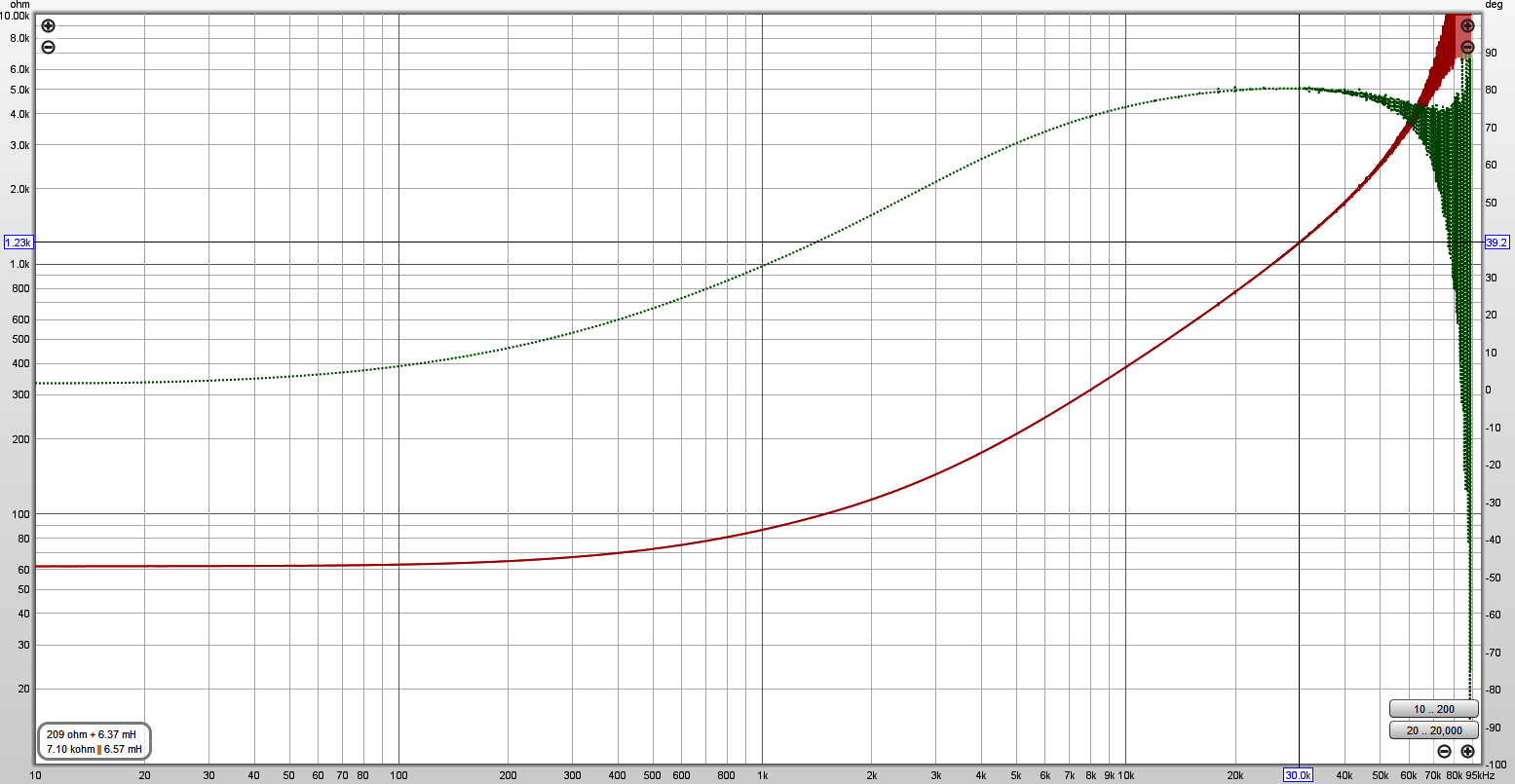
For the Ferguson PF1067 transformer, the REW plot is below (magnitude in red and phase in green) and the calculated leakage inductance (shown in the lower left corner for the position of the cross-hairs) of a half HT winding varied from 6.0mH at 10kHz to 6.4mH at 30kHz and then starts to climb towards resonance at likely circa 100kHz. The REW calculated value of the inductive component model appears valid at frequencies up to when the phase starts to fall, with the calculated value then changing to a capacitance represented model part on the other side of resonance.
I was interested to know that self resonance frequency, as it should be an upper limit if I went looking for a commutation related resonance of the power supply frequency spectrum without a snubber. It also indicated the nominal leakage inductance value that would resonate with the snubber depending on the Cx value that I wanted to use - which it did as I changed Cx and used the scope for resonance waveform assessment.
I was interested to know that self resonance frequency, as it should be an upper limit if I went looking for a commutation related resonance of the power supply frequency spectrum without a snubber. It also indicated the nominal leakage inductance value that would resonate with the snubber depending on the Cx value that I wanted to use - which it did as I changed Cx and used the scope for resonance waveform assessment.
I've waded through the whole thread but can find no mention of this. The 555 is set to 120hz, wouldn't it be better for UK and other 50hz mains countries to set the 555 to 100hz?
The last two or three times this question was asked here in this thread, the answer has been the same: Let's do some experiments. Let's find out the answer.
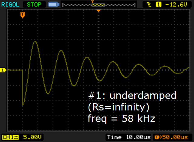
Experiment 1 is fairly simple: perform a Quasimodo test upon a transformer of your choice, with the trimmer potentiometer completely removed from its socket. (This gives Rs = infinity ohms). Adjust the triggering, offset, and gain until you get a classic Quasimodo waveform on the oscilloscope's screen.
Now, without changing the transformer or the Quasimodo jig settings, take four photos of the oscilloscope screen. The only difference between these photos is the horizontal sweep rate setting of the oscilloscope:
Please perform experiment 1, and then upload your four photos to this Forum thread. Together we'll analyze your results, and begin to understand Quasimodo better.
Experiment 1 is fairly simple: perform a Quasimodo test upon a transformer of your choice, with the trimmer potentiometer completely removed from its socket. (This gives Rs = infinity ohms). Adjust the triggering, offset, and gain until you get a classic Quasimodo waveform on the oscilloscope's screen.
Now, without changing the transformer or the Quasimodo jig settings, take four photos of the oscilloscope screen. The only difference between these photos is the horizontal sweep rate setting of the oscilloscope:
Photo 1: horizontal sweep rate is set to 5 microseconds per division
Photo 2: sweep rate = 1 milliseconds per division
Photo 3: sweep rate = 2 milliseconds per division
Photo 4: sweep rate = 5 milliseconds per division
Photo 2: sweep rate = 1 milliseconds per division
Photo 3: sweep rate = 2 milliseconds per division
Photo 4: sweep rate = 5 milliseconds per division
Please perform experiment 1, and then upload your four photos to this Forum thread. Together we'll analyze your results, and begin to understand Quasimodo better.
Just to follow up on post #2150 and #2153, I have looked at the circuit waveforms and frequency spectrum in a CLC and a C filtered full-wave ss diode rectified power supply using the PF1067 PT with 400-0-400V secondary. There was no discernible waveform detail for 400V winding leakage inductance related resonances, but there was some discernible change to the frequency spectrum noise floor - albeit only just identifiable on the winding voltage and not on the rectified and filtered voltage of the power supply.
Using 1N4004 diodes (PIV was measured the same as 1N4007) I was able to detect a hump in the frequency spectrum noise floor of the secondary winding voltage that relates to the resonant frequency of the secondary half-winding at about 60kHz. The hump moved to 48kHz with additional 470pF shunt across each half-winding, and the hump level increased by about 7dB. The hump was suppressed by about 15dB with a 4n7/1k2 RC snubber across each half-winding (for both 60kHz and 48kHz conditions). There was no specific single resonance frequency observed, only a broad hump in the region of a resonance.
Swapping to UF4007 diodes (but no snubber or shunt caps) supressed the noise floor (starting from about 20kHz up) by about 10dB and the hump at 60kHz was barely discernible.
The noise floor for the above comments is about 100dB below the mains frequency fundamental of the secondary winding (270Vpk for fundamental as testing was done at reduced mains level, but at max expected load current for application of about 150mA), with the worst hump at circa -90dB below fundamental (ie. circa 8mVpk level).
After the rectifier diodes on the first filter cap, the noise floor in that frequency region is about 30dB lower (ie. 0.1mVpk).
Last edited:
I'm designing a small first stage power supply PCB board that will have on it the following three stages only:
1) Cx, Cs and Rs (the quasimodo snubber ircuit)
2) Four diodes in a bridge
3) First reservoir capacitor
Nothing more, just a tiny board to keep the trinity of transformer, rectifier and first capacitor in very close proximity, using 2 Oz copper, wide traces. With the addition of the snubber. I have wired this circuit so many times it is about time I just made a small board for it.
My question is... What diode types are best to use? I can get anything but why not buy what is best in terms of selecting a diode that causes the least ringing for the Cx/Cs/Rs filter to deal with in the first place.
1) Standard recovery
2) Fast recovery
3) Ultra fast recovery
4) Soft recovery
5) Schottky diodes
I'm confused as to which type is "best" (by ringing the xformer bell the least).
You might or might not want to pay € 2,99 to purchase this article which shows measured ringing data on 48 different diodes, and which specifically identifies 8 of them as the "very best of the best".
Or, if you're interested in picking a good diode but not interested enough to spend € 2,99 , you can do what I now do.
IF (and only if) the rectification circuit happens to be a 4-diode fullwave bridge rectifier: buy the highest current Schottky that fits your pinout and fits your heatsink and whose voltage rating exceeds the voltage rating of your big electrolytic filter capacitors. Trust the snubber to do its job (totally eliminate the ringing), and then select a diode that drastically reduces (V * I) heat production. The load circuit determines "I", you can't do anything about it -- for you, "I" is an immutable given, a constant. Luckily the choice of diode determines "V" and you CAN do something about that -- you can pick a diode with very low forward voltage drop "V". Schottkys usually have the lowest "V" forward voltage drop, and so I now choose Schottkys, myself. But those ST Microelectronics Field Effect Rectifier Diodes ("FERD") are mighty damn good too.
You might or might not want to pay € 2,99 to purchase this article which shows measured ringing data on 48 different diodes, and which specifically identifies 8 of them as the "very best of the best".
Or, if you're interested in picking a good diode but not interested enough to spend € 2,99 , you can do what I now do.
IF (and only if) the rectification circuit happens to be a 4-diode fullwave bridge rectifier: buy the highest current Schottky that fits your pinout and fits your heatsink and whose voltage rating exceeds the voltage rating of your big electrolytic filter capacitors. Trust the snubber to do its job (totally eliminate the ringing), and then select a diode that drastically reduces (V * I) heat production. The load circuit determines "I", you can't do anything about it -- for you, "I" is an immutable given, a constant. Luckily the choice of diode determines "V" and you CAN do something about that -- you can pick a diode with very low forward voltage drop "V". Schottkys usually have the lowest "V" forward voltage drop, and so I now choose Schottkys, myself. But those ST Microelectronics Field Effect Rectifier Diodes ("FERD") are mighty damn good too.
Thanks, I was figuring on Schottky's they make them over 1,000 volts now too. Id be using this little board for both Filaments and B+ up to 500v (my personal limit) and anything else in general. To keep the noisy diode/reservoir pulse loop tight and on its own star ground away from the downstream RC/LC filter ground point.
No fuse?I'm designing a small first stage power supply PCB board that will have on it the following three stages only:
1) Cx, Cs and Rs (the quasimodo snubber ircuit)
2) Four diodes in a bridge
3) First reservoir capacitor
- Home
- Amplifiers
- Power Supplies
- Simple, no-math transformer snubber using Quasimodo test-jig