In that case replace 01A with 12at7 and check if that solves the problem.
Never mind, couple of dozens means minimum 24 units. this is tall number for many of us.
By the way, what is the output voltage of your PT?
Regards
Never mind, couple of dozens means minimum 24 units. this is tall number for many of us.
By the way, what is the output voltage of your PT?
Regards
Also pls. check your output transformer. If possible replace with a 3k/5k 4/8 ohms proven transformer. Your el84 configured as triode?
Regards
Regards
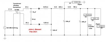
EL84 is in triode. I switched the output transformer I was using, which was a new one, to one that was once in another amp and is known to work properly. The EL84 sounds like it is buzzing steadily now at what sounds like 120 HZ. I had tried to increase the size of the power supply input cap to raise voltages a bit higher, but that resulted in the B+ voltage drifting up and down. I think John was right about oscillation in that case. The voltages now are a bit lower than I was shooting for, but they are steady. I will draw up the schematic as it now with all voltages and post it shortly.
I have a 330 Ohm on each grid. Should I increase it to 1K? Carbon comp?If not already installed pls. put 1k cc resistor at the grids of 01a and le84.
Regards
Last edited:
Your schematic doesn't show a G2 for the output stage. You might want to use a coupla-hundred Ohm resistor to connect the G2 to anode instead of a plain wire. Yeah, wierd, I know, but good practice.
YOS,
Chris
YOS,
Chris
tizman, if I am not wrong, you have two issues
Unstable B+
and
Hum
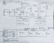
I think you should resolve unstable B+ issue first. Can you please tell us the current handling capability of the 14H and 1.5H chokes. We may run your PS in PSUDII and check if any issue there. Besides 01A is designed for 5 volt filament, why your supply is 3.69 volt? Yes CC is carbon comp.
Regards
Unstable B+
and
Hum
I think you should resolve unstable B+ issue first. Can you please tell us the current handling capability of the 14H and 1.5H chokes. We may run your PS in PSUDII and check if any issue there. Besides 01A is designed for 5 volt filament, why your supply is 3.69 volt? Yes CC is carbon comp.
Regards
The power transformer’s primary resistance is 2.1 Ohms, and its secondary resistance is 90 Ohms.
--------------------------------------
Those are good numbers, typically what we see for these small PTs used in electronic circuitry in North America where the domestic supply is 60 Hz, 120V. For Minhaj the supply is 220V, 50 Hz.
So resistance/impedance of loads becomes
R = 2E / (1/2) I…………………………….4 E/I)……………..
And another 1.2X, wire winding on the core of inductors needs to be longer to provide the higher inductance required at the lower frequency (50 Hz). So the numbers for resistance loads on the domestic supply is very different than in North America.
The variations in voltages you are seeing are a sure thing caused by the loading of the portable heaters, the current required to generate heat that way is significant. There are entire books written on the problem associated with disturbances in power systems, I have a some here in my library. A couple of the companies I worked for sold equipment used in the diagnosis & failure in power systems.
The problems you are experiencing are difficult to diagnose without a scope. But with long wires where a grid lead might be close to a plate lead could trigger parasitic oscillation of the circuit. But I think your PS is OK.🙂
I’ll stuff those numbers into the EWB simulation, report back later.
Much snow here this AM & more to go. I’ll be on the tractor soon, no heater!
Hello All.
I have a question regarding the use of DHTs as driver tubes for triode wired pentodes in a single ended amp. I have had a look online, but have not found anything about this topic. Why is this the case? Are DHTs unsuitable as drivers in this case?
If a DHT is able to properly drive a pentode wired as a triode, wouldn't the goodness of the DHT driver come through if that power tube was properly driven?
I have a reasonably good stash of 01A, 26, 71A, 30, and 31 tubes (and dozens of IDHT 27s), and I'm looking to build a small amp for use with the HF section of my horn two way speakers. The amp would do 500 HZ and up and would not require more that 2 watts of output. I can't find a single schematic that uses a DHT in the driver position, and a triode wired pentode in the power tube position.
Thanks in advance for your input on this.
Don't forget to consider the 6AQ5 which is the dual miniature rugidized 6v6 a stunningly good sounding tube. It is a must for your list!
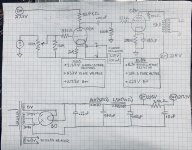
Simulated your PS as is in PSUDII 14H L 540uf C filter makes stability/Rise time slow.
You may like to change this in order of 2 uf, 1st LC10H (100R) 100uf, 2nd LC1.5H (56R) 100uf, last RC 3.5K 10uf. this will give you 270 volt B+@40ma 10m ripple current and 260 volt B++ @3ma less than 1m ripple current. Stability and rise time 3 fold better.
Regards
Regards
You may like to change this in order of 2 uf, 1st LC10H (100R) 100uf, 2nd LC1.5H (56R) 100uf, last RC 3.5K 10uf. this will give you 270 volt B+@40ma 10m ripple current and 260 volt B++ @3ma less than 1m ripple current. Stability and rise time 3 fold better.
Regards
Regards
Thanks Moray. I have many of them, and I will give the 6AQ5 a go as well.Don't forget to consider the 6AQ5 which is the dual miniature rugidized 6v6 a stunningly good sounding tube. It is a must for your list!
Simulated your PS as is in PSUDII 14H L 540uf C filter makes stability/Rise time slow.
You may like to change this in order of 2 uf, 1st LC10H (100R) 100uf, 2nd LC1.5H (56R) 100uf, last RC 3.5K 10uf. this will give you 270 volt B+@40ma 10m ripple current and 260 volt B++ @3ma less than 1m ripple current. Stability and rise time 3 fold better.
Regards
Regards
Thanks Minjhaj.
Tomorrow, I am going to start from scratch and rebuild the power supply and amp circuit. There is something wrong with the power supply that I can’t figure out. Just now, the B+ voltage dropped to 190 Volts for no apparent reason. I suspect that there is an issue with the terminal strips I am using. Time for a fresh look tomorrow.
The sim shews good agreement with your DMM measurements, 229.6V vs 225V.🙂
Something is wrong with the power supply that I can’t identify at the moment. I’m going to start over and build it neater and more carefully this time. Best I get better at breadboarding and learn how to use one of the three oscilloscopes I have at hand.
a 14H choke with 429R DC resistance may not be capable of handling 30-40ma load current. If so core will be saturated I know it will then fail to regulate but not sure if it will effect stability. Also double check all your solder joints and all the load resistors.
One easy trick to check stability of PS is to employ dummy loads (after disconnecting it from circuit load of course) and checking it with DMM.
Regards
Regards
One easy trick to check stability of PS is to employ dummy loads (after disconnecting it from circuit load of course) and checking it with DMM.
Regards
Regards
Something is wrong with the power supply that I can’t identify at the moment. I’m going to start over and build it neater and more carefully this time. Best I get better at breadboarding and learn how to use one of the three oscilloscopes I have at hand.
If you are soldering with one of the new 'no lead' solders, that could be part of the problem. They work well in mass production apps such as wave soldering but are difficult for DIY builders to work with. The melting temperatures required are higher than what we have been accustomed too. And the commonly available soldering irons may not reach the required working temperature.
All leads to poor joints. Many problems.🙁
a 14H choke with 429R DC resistance may not be capable of handling 30-40ma load current. If so core will be saturated I know it will then fail to regulate but not sure if it will effect stability. Also double check all your solder joints and all the load resistors.
One easy trick to check stability of PS is to employ dummy loads (after disconnecting it from circuit load of course) and checking it with DMM.
Regards
The Hammond choke I am using is rated for 75mA, but I will try a different choke in that position.
If you are soldering with one of the new 'no lead' solders, that could be part of the problem. They work well in mass production apps such as wave soldering but are difficult for DIY builders to work with. The melting temperatures required are higher than what we have been accustomed too. And the commonly available soldering irons may not reach the required working temperature.
All leads to poor joints. Many problems.🙁
I usually use a 63/37 eutectic solder bit in this build, many of the connections are made without soldering on terminal strips that have screws on a metal plate.
- Home
- Amplifiers
- Tubes / Valves
- DHT driver for triode wired SE EL84, 6V6 or EL34