kuroguy: When the loudest thing in the room is the power transformer in your painstakingly built DIY amp, you know it’s time to buy from another company. That said, apparently the 300 Series transformers, with multiple primary connections for worldwide use, don’t have issues with mechanical vibration. However, I haven’t bought one myself, so I can’t personally attest to it this.
I am now in the habit of plugging in every power transformer I buy before putting it into an amp. Three times burned, one time shy.
I am now in the habit of plugging in every power transformer I buy before putting it into an amp. Three times burned, one time shy.
Where is tizman. Any progress from his side?
It’s alive! It’s alive!
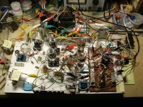
I finished the circuit and attached a crappy tester speaker and CD player to test it out. A few observations.
-in the amps current form, the output should be much more than I require, wattage wise, from a HF amp. The tester speaker is not at all sensitive, and ithe amp drives it to high volume in the near field.
-the 01A picks up vibration in the breadboard/chassis very easily and rings for a short time when the breadboard is tapped. The ringing is always the same note. That said, from my initial observations, the 01A doesn’t act like a microphone for sound in the room. It will need to be carefully isolated from any vibration.
-attached to the small, sealed 4” single driver speaker that I use for testing, there is an obvious amount of hum coming through the speaker. It is obvious and problematic with this small insensitive test speaker. There is really no point even connecting the breadboard to the high sensitivity speakers that I normally use. The hum would be unbearable. The plate choke, and it’s proximity to the circuit, appears to be one of the primary sources of the hum. Moving the choke around directly affects the volume of the hum, but with the short leads on the choke I can’t get it far enough to eliminate the hum. I will try putting the plate choke much further away to see if it is, in fact, the entire source of the hum..
-for the sort of layout/construction critical build that a DHT like the 01A requires, my relatively haphazard breadboard attempt is of limited utility. It has almost no chance of reflecting what the final product will sound like because it isn’t carefully built. I think it will come in more handy to test out IDHT builds though.
-it sounds pretty good in this limited test
I will post a drawing of the schematic of the amp in its current form shortly.
Last edited:
Congratulations! I am really happy with this. We will resolve all the issues together.
First move...replace your plate choke with same value dcr resistor to check your grounding and tell us the outcome.
Regards
First move...replace your plate choke with same value dcr resistor to check your grounding and tell us the outcome.
Regards
There has been a request in this thread, for photos of my battery biased tube amplifiers.
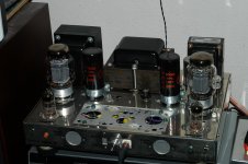
So I am attaching one photo. This is the last amplifier I built that employed battery bias, and in a way that I had never done before.
There were other battery biased, and other self biased amplifiers before this amp, but after this one, I did not use any form of battery bias again.
This amp was built on an old Dyna Stereo Chassis (I hate steel chassis).
The 2 input tubes are 6C45pi. The cathodes are connected to the ends of a 25 Ohm pot, and the pot wiper is connected to an LM317 Current Sink to ground.
One 3V lithium cell is connected from the volume control wiper to the grid stopper resistor.
In this case, I connected the negative lead to the volume control wiper, and the positive lead to the grid stopper.
The other 3V lithium cell negative was connected to ground, and the positive lead was connected to the grid stopper resistor. I did it that way to raise the two cathode voltages to give the LM317 enough voltage across it to work with signal, not just the quiescent biasing.
That is the first and only time that I used the battery + lead to the grid stopper.
All my other battery bias amplifiers had series connected batteries with the - lead going to the grid stopper.
I always did use the serial connection from signal to the grid stopper.
After this amplifier, I started using different cathode coupled phase inverter tubes, and other current sinks that had a lower burden voltage, so I did not need to use the battery bias in the way I did for this amp.
The 6C45pi tubes had matched plate load resistors.
I used RC coupling from the plates of the 6C45pi tubes to the output tubes grid stoppers.
The KT88 tubes were individually self biased, with individual bypass caps.
They were Triode wired, with 100 Ohm resistors from the screens to the plates.
The push pull output transformer was custom from Electra Print Audio (thanks to Jack Elliano).
The power supply used the original Dyna power transformer. I used 1500V solid state diodes, and the input cap was either a 1uF, 2uF, or 4uF “motor run” cap (I can not remember which, just use enough to get the B+ you want). The rest of the filter was a 5H 200mA choke, 500uF, a series resistor (100 or 180 Ohm), and another 500uF cap.
The first 500uF ran the KT88s, and the second 500uF ran the 6C45pi’s.
That should give you a little bit about the topology.
Now, for the picture (attached).
More on battery bias:
I did experiment with battery bias for output tubes too.
My first battery bias amplifier used many series 9V batteries to bias 300B tubes.
I also did a 2A3 amp with battery bias, there were Five 9V batteries from the volume control to the grid stopper. But I used an AC powered filament.
If I ever do a 2A3 amp again, it will have a DC powered filament, and self bias.
Attachments
Last edited:
Your breadboard arrangement is much better organized and quite spacious compared to mine and I'm having none of the issues you mention.It’s alive! It’s alive!
I finished the circuit and attached a crappy tester speaker and CD player to test it out. A few observations.
-the 01A picks up vibration in the breadboard/chassis very easily and rings for a short time when the breadboard is tapped. The ringing is always the same note. That said, from my initial observations, the 01A doesn’t act like a microphone for sound in the room. It will need to be carefully isolated from any vibration.
-attached to the small, sealed 4” single driver speaker that I use for testing, there is an obvious amount of hum coming through the speaker. It is obvious and problematic with this small insensitive test speaker. There is really no point even connecting the breadboard to the high sensitivity speakers that I normally use. The hum would be unbearable. The plate choke, and it’s proximity to the circuit, appears to be one of the primary sources of the hum. Moving the choke around directly affects the volume of the hum, but with the short leads on the choke I can’t get it far enough to eliminate the hum. I will try putting the plate choke much further away to see if it is, in fact, the entire source of the hum..
-for the sort of layout/construction critical build that a DHT like the 01A requires, my relatively haphazard breadboard attempt is of limited utility. It has almost no chance of reflecting what the final product will sound like because it isn’t carefully built. I think it will come in more handy to test out IDHT builds though.
I will post a drawing of the schematic of the amp in its current form shortly.
Here's a pic. 😱 Quite frankly, it's embarrassing. I gotta put together a more organized breadboard at some point. But if this setup is dead quiet, there's no way your breadboard is the source of the problems you're having. There's gotta be something else going on.
Perhaps it's because I'm using an ST version of the 01A. Are you using a globe?? I've heard that globe versions of all these old tubes are much more microphonic than their ST versions.
I get no ring when I tap quite hard on the breadboard itself or the table it's on. When I tap the tubes I get a very brief ring but it disappears quickly. I don't consider this an issue since I don't tap on tubes during normal operation of an amp. I've had indirectly heated tubes, like the 12B4, that actually ring much more.
As minhaj pointed out earlier, chokes need to be designed as plate loads, so resistor loading may solve the hum problem. I'm using the cheap Hammond 156Cs and they're randomly placed right in the middle of a my mess of a breadboard. No hum. But they are designed as plate chokes.
Since your PT is vibrating, could it also be the source of the hum? You might try using a different one or a bench supply if you have one. I build using scrounged parts. The PT in mine was rescued from a dead R2R recorder. I ran this amp for ~12 hours straight and the PT barely gets warm at all. I'll use a scrounged vintage transformer every time if its specs allow.
I know you're building this as a tweeter amp. If you have a crossover of some type installed could that be causing a problem? My bench speakers are maybe 90-92db so I can't say what might be audible with 100db+ drivers, but mine is dead quiet right now.
I'm using the same basic setup as the schematic I posted earlier (post #36) that uses the 26 as input tube. The only difference is that I'm using a 5v version of the Meanwell SMPS, a 0B2 voltage regulator in place of the 0A2, and -4.5v battery grid bias instead of -9.78v. Plate voltage is ~98v and each 01A is running at ~3mA.
Attachments
Last edited:
FlaCharlie: Thanks for your input. I’m thinking that the cause of the hum might be excessive ripple in the power supply. I am using a bench supply that was made by someone else, and it had around 1.5 volts of ripple on the output. I added a CLC on the output (40uF/10H/70uF) and figured that would get rid of the ripple, but I just remeasured the B+ with a DMM set to AC and it is still just over 1 volt, which doesn’t make sense to me. The choke is now on extended leads and is nowhere near the breadboard. The 6.3 Volt transformer that was vibrating was swapped out for one that doesn’t vibrate, and moved off the board. I’m going to do what I should have done in the first place and also breadboard the proper power supply as I designed it. I have four 01A on hand. The hum coming out of my test speaker doesn’t change, regardless of which one of the four is plugged in. The length of the ringing when the breadboard is tapped does change though. They are all sensitive to vibration. All 4 are globes. The final amp will be set up to accept both 26 and 01A tubes, and possibly 31 as well. Euro21 provided a schematic earlier in this thread that shows an amp that has Ale’s gyrator and a Rod Coleman filament regulator on the driver tubes, and a switch to go from 01A to 26. I have more 26 tubes than 01A....
Minjah: Thanks for the encouragement! I will try swapping the choke out for a resistor as you suggest.
I will breadboard the PS, draw up the entire circuit and report back.
Minjah: Thanks for the encouragement! I will try swapping the choke out for a resistor as you suggest.
I will breadboard the PS, draw up the entire circuit and report back.
tizman, try whatever you wish to solve the issues. At the end if you need help speak out loud we will help you. If the PS is not good enough nothing will work.
Your approach, in my opinion, is the cause of the problem. Please don't get me wrong. You need to design and build a proper power supply first.
Your approach, in my opinion, is the cause of the problem. Please don't get me wrong. You need to design and build a proper power supply first.
“You need to design and build a proper power supply first.“.
Yes. I should have started off with the right one. It will be done in a little while, and I’ll report back.
Yes. I should have started off with the right one. It will be done in a little while, and I’ll report back.
6C45 PI
Doesn't appear in the frank.pocnet list. Does anyone have a data sheet on this Soviet vacuum tube? THX🙂
Doesn't appear in the frank.pocnet list. Does anyone have a data sheet on this Soviet vacuum tube? THX🙂
THX Hearing Space
This tube looks like something we would find in the front end of an HF or VHF receiver. But plenty of gain & low drive point impedance to the following stage is a benefit. And with what looks like a very linear plate family, should do well as the front end of a power amp, SE or PP.
From 6A3s description, I get the sense that both grids of a diff amp are elevated 3V above common. Very strange indeed. Normally if the diff amp plate loads are correct, both grids can be left at the common voltage, bias is accomplished simply by the current set by the cathode tail, in this case the LM317.
What was the LM317 tail current set at & what are the diff amp plate loads?🙂
The low capacity of the first cap after the rectifier so long as the amp is running in Class A. From the description it is.
Very early on (1950), I tried battery biasing in a power amp. After a time the power tubes red plated. Never again!😱
More 6A3 Amp
Was the diff amp tail taken to common or the -ve grid supply that provide bias to the power tubes?
Was the diff amp tail taken to common or the -ve grid supply that provide bias to the power tubes?
'Yes. I should have started off with the right one. It will be done in a little while, and I’ll report back.'
Thanks. Also try with a properly sized plate resistor (min.3x plate impedance of the loading tube) once everything is fine replace with a plate choke. But...I never heard of a 2/3/4 H plate choke. Please focus on your project and keep it simple for the initial power up.
Wish you will be successful very soon.
Regards
I replaced the plate choke with a resistor of the same resistance as the choke, but hum was only reduced and not eliminated. I will try a resistor on the plate. Plate resistance is 10K for the 01A, so 30-40K?
Was the diff amp tail taken to common or the -ve grid supply that provide bias to the power tubes?
I mistakenly assumed the diff amp tail would be taken to a negative supply, something I've always done. But some are not, the most common I can think of is in the Mullard series of amps. So for 6A3s amp the 3V cells would work. For those who would like to avoid the batteries refer to the attachments for a clean solution.🙂 And apologize for inserting this into Tizman's thread.
Attachments
As minhaj said . . . rule of thumb for resistor plate load is minimum 3x the plate resistance but 5x would be better.I replaced the plate choke with a resistor of the same resistance as the choke, but hum was only reduced and not eliminated. I will try a resistor on the plate. Plate resistance is 10K for the 01A, so 30-40K?
PS will need to be designed so that you have the desired plate voltage. The supply will need to be higher than what you had since the choke you were using only had, what, 2.3k DCR or something like that. I'd suggest that you use PSUD2 to sim it first.
Was this battery cathode bias or battery grid bias? Why would the source of voltage affect the output tubes? Wouldn't they be just as likely to red plate with a traditional negative supply that produced the same voltage? Or was the voltage from the battery unstable?Very early on (1950), I tried battery biasing in a power amp. After a time the power tubes red plated. Never again!😱
There has obviously been a lot of progress in battery technology since 1950 too.
I only use battery bias on input tubes and prefer it on the grid for reduced maintenance. I tried battery cathode bias on some output tubes and the battery couldn't handle the current. Luckily I caught it before it went boom but it was close. The battery, a 9v, was bulging when I checked it.
I haven't tried diodes yet but plan to at some point. I've been hesitant since some users claim they produce an edgy, somewhat harsh, character to the sound.
'I haven't tried diodes yet but plan to at some point. I've been hesitant since some users claim they produce an edgy, somewhat harsh, character to the sound.'
I tried infra-red LED and Cree carbide diode. I prefer carbon film resistor bypassed with Elna Silmic II.
tizman...you need 270volt at 40ma for el84 and 250volt at 3ma for 01a. A 50k 2 watt plate resistor will drop (50,000X.003) 150volt. Please design a PS using PSUDII and proceed from there.
Regards
Charlie....I use heavily modified Fostex 206 in 208 sigma BL cab. Diode bias may sound better in a regular 2 way with passive crossover. This is all about personal liking and system synergy.
Regards
Regards
Exactly. YMMV always holds true. There are just too many variables between systems, rooms, music and listeners.Charlie....I use heavily modified Fostex 206 in 208 sigma BL cab. Diode bias may sound better in a regular 2 way with passive crossover. This is all about personal liking and system synergy.
Regards
When you tried diodes was it on input tubes, output tubes or both? Ever tried battery bias?
- Home
- Amplifiers
- Tubes / Valves
- DHT driver for triode wired SE EL84, 6V6 or EL34