Input tube mostly E180F, E810F, EF184 triode connection.
Ok coming holiday I try battery bias and tell you if I like it. I really like filament bias which is employed in my DHT pre.
Ok coming holiday I try battery bias and tell you if I like it. I really like filament bias which is employed in my DHT pre.
Tizmans PS EWB Solution
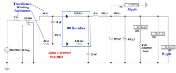
A first pass shewing the resultant DC & AC potentials at the load & after the first LC filter section. There are no vacuum rectifiers in EWB, altho it can be tricked by using a low mu tiode such as a 6080 as a starting point. So the 80 rectifier is simulated by a pair of silicon diodes & series resisters,
The halves of the PT are different resistances since the HV winding is done serially, the 2nd half wire length is longer since it is wound over the first half. This results in a line frequency component in the ripple that is not filtered as well as the rectified ripple. The LC filter sections are 12 db less effective at the line frequency. At times this causes a problem tor SET amplifiers if the line frequency is close to one of the loudspeaker resonances in their system. No problem in this case, any resonances are far away.🙂
Attachments
Was this battery cathode bias or battery grid bias? Why would the source of voltage affect the output tubes? Wouldn't they be just as likely to red plate with a traditional negative supply that produced the same voltage? Or was the voltage from the battery unstable?
There has obviously been a lot of progress in battery technology since 1950 too.
I only use battery bias on input tubes and prefer it on the grid for reduced maintenance. I tried battery cathode bias on some output tubes and the battery couldn't handle the current. Luckily I caught it before it went boom but it was close. The battery, a 9v, was bulging when I checked it.
I haven't tried diodes yet but plan to at some point. I've been hesitant since some users claim they produce an edgy, somewhat harsh, character to the sound.
Hey Charlie, I did this so long ago I actually still had hair, a lot of it! It was based on an 815 PP amp. Lots of current in the cathode, at that point in time I'd never heard of stuffing a battery in the cathode. Rechargeable batteries in those daze used very corrosive liquids as electrolytes, not a great idea at all.
So the battery which wuz called a 'C' battery at the time was a common 22.5 v Zinc-Carbon thing with several taps to satisfy biasing of several common battery operated tubes. It had been in my stash for a while & somewhat abused, so didn't last long in that PP 815 amp. The bias was applied thru the CT of a PP secondary of a Hammond 447 IT. Its still here in my stash & is handy for experimental setups I often try. But never with battery bias of either kind, there are better ways.🙂
Someone should take the time to do objective tests on those diode bias schemes. All diodes are non-linear, altho over the short delta in current seen in a preamp stage might be OK. But measurements of DHT & IMD would be a great idea at some point. And why would a red LED sound better than a Germanium Diode. And don't bother doing it on a power amp, the difference between diode resistance at low current & high current could be very large.😱
But someone will anyway & then tell us which way 'sounds' better.
Attachments
Follow on of my Post # 144:
For the push pull 6C45pi-E and KT88 amplifier, I did not want to have to use all the parts that it takes to have a negative power supply, for the LM317 current sink. So I used Positive battery bias.
Using the positive battery bias, the grids of the 6C45pi-E were at about +3.25V.
But there was no appreciable grid current, because the cathodes self biased in concert with the LM317 current sink.
The current source was set for 20mA; 10mA per 6C45pi-E.
The 6C45pi-E plate loads were 19.1k (at least as well as I can remember).
The KT88 tubes were Triode wired, and drove a 6000 or 6600 plate to plate output transformer.
There was no negative feedback used (Well, the Triode wiring is negative feedback).
The 6C45pi-E tubes had 2nd order distortion cancellation, because of the cathode to cathode connection, and the LM317 current sink.
Last edited:
The keys to successfully using negative battery grid biasing of output tubes are:
Do not use the tube near its maximum plate dissipation (and if present: screen dissipation limits).
Do not use the tube near its maximum plate voltage (and if present: screen voltage limits).
Do not let the g1 resistance to ground be near to the maximum specified g1 resistor for Fixed Bias (the Battery is fixed bias, not self bias).
Design your amplifier to normally operate in Class A1, AB1, etc. Do not design it to be regularly drawing grid current (Class A2, AB2, etc.).
Put the battery in series from signal to the grid. Do not put the battery positive to ground, and the battery negative to the bottom of the grid return resistor, Rg. That will cause signal current, however small, to constantly charge and constantly discharge the battery.
Isolate the battery shell from the chassis. Even a few 9V batteries that use double sticky tape to mount to the chassis, will have a low enough capacitance to ground for most circuits. Do use a capacitance meter to measure that, so you know what the amount of the stray C is, and calculate the effect it has on your circuit.
Use quality fresh modern Lithium or fresh modern Alkaline batteries.
Check your battery voltage once every year.
Follow these rules, and enjoy your battery biased amplifier.
Gee, I remember several jobs where our test equipment had to be fully checked out and calibrated every 6 months.
And, much of that equipment did not have batteries.
An interstage transformer that drives output tube grids generally can draw grid current (Class A2, AB2, etc.).
And that draws battery current (charge, discharge, or both depending on the circuit).
Generally not a good amplifier candidate for battery bias.
Last edited:
A first pass shewing the resultant DC & AC potentials at the load & after the first LC filter section. There are no vacuum rectifiers in EWB, altho it can be tricked by using a low mu tiode such as a 6080 as a starting point. So the 80 rectifier is simulated by a pair of silicon diodes & series resisters,
The halves of the PT are different resistances since the HV winding is done serially, the 2nd half wire length is longer since it is wound over the first half. This results in a line frequency component in the ripple that is not filtered as well as the rectified ripple. The LC filter sections are 12 db less effective at the line frequency. At times this causes a problem tor SET amplifiers if the line frequency is close to one of the loudspeaker resonances in their system. No problem in this case, any resonances are far away.🙂
Thanks! I am going to give it another go this evening. At the moment, the power supply has almost 1 volt of ripple at its output rather than what it should based on your simulation and mine. I don’t have a great way to test capacitors, so they may be the problem. I’ll try again with the brand new caps I have at hand.
'I haven't tried diodes yet but plan to at some point. I've been hesitant since some users claim they produce an edgy, somewhat harsh, character to the sound.'
I tried infra-red LED and Cree carbide diode. I prefer carbon film resistor bypassed with Elna Silmic II.
tizman...you need 270volt at 40ma for el84 and 250volt at 3ma for 01a. A 50k 2 watt plate resistor will drop (50,000X.003) 150volt. Please design a PS using PSUDII and proceed from there.
Regards
The currently breadboarded supply uses a small cap at the input to lower voltage to where I need it, so I have room to get the voltage where I want. Because I am breadboarding one channel, I need to design for one channel in PSUD2. I forgot about this when I did it the last time. I will try a resistor on the plate and modify the power supply to get what I need in voltages.
I mistakenly assumed the diff amp tail would be taken to a negative supply, something I've always done. But some are not, the most common I can think of is in the Mullard series of amps. So for 6A3s amp the 3V cells would work. For those who would like to avoid the batteries refer to the attachments for a clean solution.🙂 And apologize for inserting this into Tizman's thread.
It's all good. Alternate methods of biasing is something that I would like to try in this amp as well. Baby steps for me now though...
Response to FlaCharlie post #85
Thanks for the additional info, John. I was aware that the combination of the 76 and 6AC5 could be used to mimic the 6N6G. It hadn't occurred to me that a pentode like the 6F6 could be used in triode mode. It's nice to have the two triodes contained in a single bottle, of course, but those are all great alternatives.
A few questions . . . In one of the attached documents you said, "most power pentodes when run as triodes with G1 & G2 strapped together have quite a high mu."
I've only seen triode strapped pentodes with G2 connected to the plate, typically with a 100 ohm resistor. Is this a misprint or can G2 be connected to G1 also? If so, I assume no resistor is necessary. Correct?
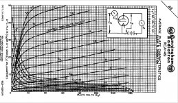
Not a misprint, the circuit is connected as shewn. Quite a few power pentodes can be connected in three different ways. In the early to mid thirties several tubes were developed & circuits devised to use them. Often the ordinary triode hookup as the driver, the low impedance of the triode version is required in that position. Refer to the 46 & 49 sheets.
Does connecting G1 & G2 result in higher mu than with a G2 & Plate connection? If so, then a pentode could effectively be used to produce 3 different levels of mu, depending on how it's wired, not just 2.
The mu is higher & so is the plate resistance. The result is very pentode like. Complete with the pentode knee. The loudspeaker damping is poor, just as it is while operating as an ordinary pentode.
The 6F6 tested rp of 15K with the plates tied together & 51K in the pentode mode.
The mu was 13 with the plates tied together, a result of the driver 6SN7 mu of 20. Those numbers are related. The pentode mu was ~36.
And, you mentioned that the plate of the input triode can be connected to B+, as I did, or to an UL tap, as you suggested, but you also mentioned it could be connected directly to the plate of the output triode. What advantage is there to connecting the input plate to either an UL tap or the plate of the output section? Are there any disadvantages to either method?
When the two plates are connected together the composite tube becomes an ordinary low mu triode, just as a pentode does when the screen is connected to the plate.
Also, I was aware of the 25B5 and 25N6G but I had never looked at their data sheets. Oddly, while the 6N6G has a max plate voltage of 325v, the 25N6G has a maximum of only 180v. Any idea why? I would have expected them to be the same except for the heater.
The 25N6G was meant to be stuffed into the same circuit as a 25L6 so as to operate in AC/DC radios.
As you point out, the base of the 6N6G is the same as many common power tubes. I recently modded a Magnavox PP 6V6 amp to use 6N6Gs with excellent results. Here's a link to that build. It's ugly but it sounds great. If I had known it was going to sound so good I would have gussied it up.
Magnavox 175/185 Build . . . With a Twist | Audiokarma Home Audio Stereo Discussion Forums
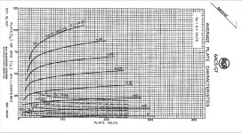
I've posted the pentode plate curves as JPEGS as well for the convenience of those who appear to be terrified by the prospect of opening a PDF.
Thanks for the additional info, John. I was aware that the combination of the 76 and 6AC5 could be used to mimic the 6N6G. It hadn't occurred to me that a pentode like the 6F6 could be used in triode mode. It's nice to have the two triodes contained in a single bottle, of course, but those are all great alternatives.
A few questions . . . In one of the attached documents you said, "most power pentodes when run as triodes with G1 & G2 strapped together have quite a high mu."
I've only seen triode strapped pentodes with G2 connected to the plate, typically with a 100 ohm resistor. Is this a misprint or can G2 be connected to G1 also? If so, I assume no resistor is necessary. Correct?
Not a misprint, the circuit is connected as shewn. Quite a few power pentodes can be connected in three different ways. In the early to mid thirties several tubes were developed & circuits devised to use them. Often the ordinary triode hookup as the driver, the low impedance of the triode version is required in that position. Refer to the 46 & 49 sheets.
Does connecting G1 & G2 result in higher mu than with a G2 & Plate connection? If so, then a pentode could effectively be used to produce 3 different levels of mu, depending on how it's wired, not just 2.
The mu is higher & so is the plate resistance. The result is very pentode like. Complete with the pentode knee. The loudspeaker damping is poor, just as it is while operating as an ordinary pentode.
The 6F6 tested rp of 15K with the plates tied together & 51K in the pentode mode.
The mu was 13 with the plates tied together, a result of the driver 6SN7 mu of 20. Those numbers are related. The pentode mu was ~36.
And, you mentioned that the plate of the input triode can be connected to B+, as I did, or to an UL tap, as you suggested, but you also mentioned it could be connected directly to the plate of the output triode. What advantage is there to connecting the input plate to either an UL tap or the plate of the output section? Are there any disadvantages to either method?
When the two plates are connected together the composite tube becomes an ordinary low mu triode, just as a pentode does when the screen is connected to the plate.
Also, I was aware of the 25B5 and 25N6G but I had never looked at their data sheets. Oddly, while the 6N6G has a max plate voltage of 325v, the 25N6G has a maximum of only 180v. Any idea why? I would have expected them to be the same except for the heater.
The 25N6G was meant to be stuffed into the same circuit as a 25L6 so as to operate in AC/DC radios.
As you point out, the base of the 6N6G is the same as many common power tubes. I recently modded a Magnavox PP 6V6 amp to use 6N6Gs with excellent results. Here's a link to that build. It's ugly but it sounds great. If I had known it was going to sound so good I would have gussied it up.
Magnavox 175/185 Build . . . With a Twist | Audiokarma Home Audio Stereo Discussion Forums
I've posted the pentode plate curves as JPEGS as well for the convenience of those who appear to be terrified by the prospect of opening a PDF.
Attachments
-
 6AC5GT Plate Family.jpg368.6 KB · Views: 90
 -
 6L6 PP Screen Drive Circuit Patent 1945.jpg76.8 KB · Views: 214
 -
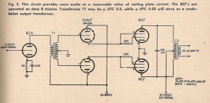 807 Modulator.jpg47.8 KB · Views: 218
 -
 49 Plate Family Zero Bias.jpg199.9 KB · Views: 205
 -
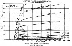 46 Plate Family Class B.jpg164.2 KB · Views: 207
 -
49 RCA.pdf172.6 KB · Views: 73
-
46 Cunningham.pdf324 KB · Views: 75
A quick question that I can't seem to find an answer for. What is the maximum plate dissipation of the 01A?
No spec for Pd was given or seems to have been published for many of the early tubes. Unfortunately, Alan Douglas who probably could have helped us died a few years ago.
But could be held to a safe limit with at least 27K running from a 250V supply. If the plate settled at 1/2 that the PD would be (125V)* (4mA) ..............or 500 mW.
There is a power version & high mu version covered in the attachment.
But could be held to a safe limit with at least 27K running from a 250V supply. If the plate settled at 1/2 that the PD would be (125V)* (4mA) ..............or 500 mW.
There is a power version & high mu version covered in the attachment.
Attachments
Thanks John. It's odd not seeing a Pd on any of the spec sheets I found for 01A and its equivalents.
tizman
I agree with john, 125 volt at the plate will be fine. You may consider 3 mA instead of 4mA because at that point dissipation will be tad lower and you don't need any more as el84/6v6 driver.
Regards
I agree with john, 125 volt at the plate will be fine. You may consider 3 mA instead of 4mA because at that point dissipation will be tad lower and you don't need any more as el84/6v6 driver.
Regards

A quick update. I couldn’t figure out what the problem was with hum, so I rebuilt the power supply for the voltages that would work with a plate resistor and removed the plate choke and replaced it with a 47K Ohm resistor. My voltages are lower than predicted by PSUD2, so I will adjust the capacitor input to raise them to where I want them. There is still some hum through the speaker, but it is much reduced, and possibly from hum being picked up from the open unshielded breadboard.
The EL84 output tube is making a quiet chattering sound, and it does this with any EL84 that I plug into the socket. This is not heard through the speaker, but comes from the tube itself. From my position at about two and a half feet from the tube, the chattering sound is audible when the music is off. This has never happened in any of my regular builds into a chassis. Is this the EL84 oscillating or the 01A’s oscillation being heard through th EL84? Again, it isn’t audible through the speakers.
The EL84 output tube is making a quiet chattering sound, and it does this with any EL84 that I plug into the socket. This is not heard through the speaker, but comes from the tube itself. From my position at about two and a half feet from the tube, the chattering sound is audible when the music is off. This has never happened in any of my regular builds into a chassis. Is this the EL84 oscillating or the 01A’s oscillation being heard through th EL84? Again, it isn’t audible through the speakers.
The only times I've ever heard a tube make a sound is during warmup. And only on large tubes. If every tube tried is making the same sound that normally would indicate something else is causing that sound. If the circuit is self oscillating that may appear as a drifting up & down if the HV is measured on your DMM.
For the PS pls check the DC resistance of the primary & secondary HV windings, I'll plug that back into the EWB simulation. The measured HV might be lower than the calculated value since the EL84 is pulling heater current from your PT as well, that loads the primary & the end result shews up on the final HV measurement. These simple simulation don't make any allowance for that.
For the PS pls check the DC resistance of the primary & secondary HV windings, I'll plug that back into the EWB simulation. The measured HV might be lower than the calculated value since the EL84 is pulling heater current from your PT as well, that loads the primary & the end result shews up on the final HV measurement. These simple simulation don't make any allowance for that.
The power transformer’s primary resistance is 2.1 Ohms, and its secondary resistance is 90 Ohms. The B+ voltage at the plate of the EL84, as measured by my DMM, drifts around a bit, but the drift seems to be a product of other items that share the circuit. When my portable electric heater on the same circuit turns on, the B+ drops by 15 Volts. Measured with the heater off, the voltage does still move around. Over the course of a one minute period, the voltage went from 207.9 at the start to 211.2 at the end. In the next 2 minute period the voltage moved between 210.8 and 211.2. My feeling is that the fluctuations are due to the 6 portable heaters in the house turning on and off.
We need a schematic for signal circuit + PS circuit with voltage and current reading to help you. Usually el84 type tube don't oscillate, same for 01A. Primary for your PT should not be 2.1 ohms pls double check it. Chattering sound/any sound from tube is unusual-something is wrong here. This is a simple circuit why it is giving you this much trouble I don't understand.
Is this your first (complete amp) build? Room heaters- you have nothing to do here unless troublesome house power wiring change. If nothing works I am ready here to hold your hand for scratch build. In that case you should hold one guides hand not many.
Regards
Is this your first (complete amp) build? Room heaters- you have nothing to do here unless troublesome house power wiring change. If nothing works I am ready here to hold your hand for scratch build. In that case you should hold one guides hand not many.
Regards
I will post the schematic for circuit and power supply shortly. I have built a couple of dozen amps, just not on a breadboard and not with DHTs. All the amps I have built were two stage, single ended designs using indirectly heated tubes, built into their final chassis. I measured across the two primary black wires of my power transformer, and it measures 2.1 Ohms. I have three of these power transformers, and all three measure 2.1 Ohms across the two black primary wires that are connected to mains.
- Home
- Amplifiers
- Tubes / Valves
- DHT driver for triode wired SE EL84, 6V6 or EL34