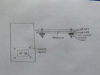
Each old DHT "requiring" the relatively heavy weight sub-platter (4-10mm aluminium), which fastened with suspended bolts to top platter.
See Vinylsavor solutions.
I have the bolts pictured on hand, and may use them as well, but I think that the plan I have using constrained layers and Green Glue will work well.
Didn't have any microphonics with my modular system, 4mm top plates and wooden sides. The modular top side cuts down transmission with one plate detached from the next.
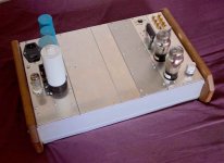
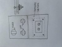
That’s a great idea Andy! I normally build with a wooden frame and a single thick aluminum top plate suspended above it on on a spacer, so there is a gap all the way around the perimeter of the top plate. This gap, combined with a perforated bottom plate, allows for lots of ventilation for the components inside the amp. Check out the attached photos. Splitting up that top plate is easy enough and looks like a good plan. It’s not something that has been required with IDHTs, but I’ve never encountered anything remotely like the microphonics of the 01A in any IDHT I have encountered.
Attachments
Last edited:
I use 19" sub rack parts for everything. I use horizontal rails in a vertical way, so the top plates can screw into the threaded inserts. Easy to swap plates about. I don't need to breadboard - I just make something on a plate and screw it in. I have loads of ready made plates by now. 275mm long and 50mm, 70mm or 100mm wide. 4mm soft aluminium.
Dividing the top plate will further reduce the chances of the tubes picking up vibrations from the magnetics.
Attachments
Last edited:
Andy: What are “19" sub rack parts”?
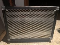
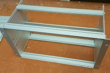
Think of a 19" rack, like you see in studios. 19 inches across and full of units like preamps, amps, effects etc. screwed in on both sides in a vertical arrangement. The sub racks are the individual units, photo attached. They're made up of a lot of threaded strips which screw together like Meccano. You can make anything out of the parts and they look nice in silver anodised aluminium.
Attachments
andyjevans: Thanks for the details. Making the top plate out of a number of different plates is a great idea. It allows for swapping out portions of an amp without having to redo the entire thing. A plate each for the PSU, output transformers, power tubes and driver tubes allows for quick swaps of each section. Adding a blank section or two for future stages or other uses makes it even more flexible. Thanks for the idea.
Andy: What are “19" sub rack parts”?
andyjevans: Thanks for the details. Making the top plate out of a number of different plates is a great idea. It allows for swapping out portions of an amp without having to redo the entire thing. A plate each for the PSU, output transformers, power tubes and driver tubes allows for quick swaps of each section. Adding a blank section or two for future stages or other uses makes it even more flexible. Thanks for the idea.
Yes, exactly this as you say. And each plate is so easy to work on - you're not having to work on the whole chassis all the time. I found 50mm, 70mm and 100mm convenient widths. I chose 275mm length because it gave me a total front to back size of about one foot (300mm) which I judged would fit any shelf. All my connectors are at the top, on the plates themselves. That helps a lot. I chose 4mm in soft aluminium because it's easier to work on in terms of drilling and using hole saws. You could use 3mm in a harder grade, which is more silvery and doesn't scratch so easily. Soft alluminium is more white-ish. I chose 2U (88mm) as the depth but you could use 3U for a deeper chassis. 1U is a bit restrictive. You can use front panels in these sizes - usually black. Can also be ventilated or mesh. And then fit handles on the front that fit the 2 holes on each side. Standard width of the 84HP horizontal rails is 430mm. For the side pieces you can use wood or metal. You could consider 4"x1"x1/8" aluminium angle which would give you a lip on either side to lift the amp with.
You should find some used horizontal rails or complete sub racks if you look about on auction sites etc. You need the horizontal rails and the threaded inserts, which are 3mm or 2.5mm screws. Google on 19" or 2u, 3u, 4u etc, maybe subrack or rack, and see what turns up. Or look for a basic kit. 3U is much more common than 2U. Handles are called "D bar" if you google that. Width between holes for 3U is 57mm.
https://uk.rs-online.com/web/p/subracks/4691098/
Last edited:
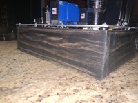
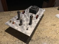
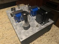
andyjevans: Thanks. I will definitely look into it. My current top plates are 3mm aluminum, but I’m not sure if they are hard or soft. I have been finishing the panels with a metal brush on a drill for a while now. I hate painting chassis, and I prefer the look of raw metal, but keeping aluminum scratch free is difficult, so I tried this technique a while back and have stuck to it. It is basically immune to showing scratches and fingerprints. Attached are photos of two different amps that I used this finishing method on to give you an idea of what it looks like. It is much less glitzy looking in real life.
Attachments
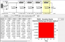
A quick question. I breadboarded the CLCLCLCLC filament supply that is in the attached PSUD2 screenshot, and measured it, but the results don’t make sense to me. When filament is adjusted to 2 Volts, as measured with my multimeter, the current as measured across the two pins of the filament is around 150mA. In comparison, when I connect the Coleman regulator and set it to 2 Volts, the current across the two filament pins is 60mA. Why am I getting this variation in current between the Coleman and the supply I put together? This happens with all the 30 tubes I have tried. Is this a measurement error on my part?
Attachments
Last edited:
A quick question. I breadboarded the CLCLCLCLC filament supply that is in the attached PSUD2 screenshot, and measured it, but the results don’t make sense to me. When filament is adjusted to 2 Volts, as measured with my multimeter, the current as measured across the two pins of the filament is around 150mA. In comparison, when I connect the Coleman regulator and set it to 2 Volts, the current across the two filament pins is 60mA. Why am I getting this variation in current between the Coleman and the supply I put together? This happens with all the 30 tubes I have tried. Is this a measurement error on my part?
Have you read all the instructions for the Coleman boards thoroughly? Are you using normal bias or filament bias? If normal bias you want the right resistor in the board for the particular tube - should be the one in the right hand corner. For 60ma this should be around 15 ohms, half watt. You want around 5v headroom for the reg to work, and then you just adjust the trim pot until you get the right voltage on the filament pins, 2v. For filament bias the current is the same, so same resistor, but the input voltage will be higher. So if bias is 4v, add 2v and you have 6v coming out of the reg and around 11v going into it. I hope Rod can confirm this - all this is off the top of my head.
Since the Coleman regs are apparently working, you must have done all this. Why not just stick to these boards?
Last edited:
Excellent chassis construction tips for use with any tubes, not just those that are microphonic.
I've noticed some puzzling behavior by microphonic tubes and I'm wondering if others have also experienced this.
Two examples . . . I mentioned earlier that I had tried using the 1LE3 when I was breadboarding a basic preamp, and yesterday I tried some 31s with my current 6N6G SET.
The 1LE3 was so microphonic that lightly rubbing my finger across the front surface of the volume knob could be heard through the speakers! The 31s were not quite as microphonic but tapping on the breadboard was audible. And, obviously, tapping a tube creates a ping just as it does with many other tubes, including some indirectly heated varieties.
What surprised me was that, in both cases, I couldn't hear any issues when music was playing. I expected, especially with the 1LE3, that the tube would start howling after music was playing for a while. Or that some residual ringing could be heard when I paused the music. But they both behaved normally as far as I could tell.
This makes me wonder if microphonics is that much of an issue in a "real world" normal listening environment. My breadboard is positioned right between the speakers. The tubes themselves are about 16" in front of the speakers and around 24" from each cone - closer than they would ever be in a listening setup. Granted, I don't listen at rock concert level volumes.
Are audible issues with microphonics really that common in a normal setup when you're not tapping on the tubes or the chassis?
I've only had it happen with a junkbox preamp I built that used 12B4s, which is an indirectly heated tube, but only some of them were that microphonic.
Last edited:
A quick question. I breadboarded the CLCLCLCLC filament supply that is in the attached PSUD2 screenshot, and measured it, but the results don’t make sense to me. When filament is adjusted to 2 Volts, as measured with my multimeter, the current as measured across the two pins of the filament is around 150mA. In comparison, when I connect the Coleman regulator and set it to 2 Volts, the current across the two filament pins is 60mA. Why am I getting this variation in current between the Coleman and the supply I put together? This happens with all the 30 tubes I have tried. Is this a measurement error on my part?
Are you measuring current using the meter in current-mode? This often means the current has to flow through long leads. The leads can sometimes acquire some ac voltage from nearby transformers or chokes, and corrupt the reading. Alternatively, the actual value of voltage across the filament, when fed with chokes might be unstable.
Usually, a DMM reading that is apparently giving an impossible value is corrupted by some kind of AC augmentation.
No need to connect current-probes to measure current with my regulators: just measure the voltage across R1; then I = V(R1)/R1,Ω
Another consideration with CLCLCLC...
The values of 3mH and 2.5mF in themselves are a resonant tank (at f = 1/(2П.(LC)^0.5). The resonance may not be very high Q, but it will still peak in the low kHz region. Resonance in this case means high impedance, and given the physical size of the chokes, there may be some noise buildup from that route.
It also means that the impedance looking out from the filament is not flat with frequency, and sees an impedance peak at that point too. The filament has a differential signal across it (caused by difference in gm at each end), and it is likely to impose some unexpected EQ on the signal (mid-range). You can compare the sound with my regulator to gauge this effect.
A good cook is capable of preparing a delicious dish out of ordinary ingredients. As I hinted earlier, CLCLCLCLC should give you trouble, specially with very high value C. CLC or LCL is good enough (I prefer LCL), at best you can add another pi filter. If Rod's supply is working fine stick with that and proceed to make the circuit operational. You need to spend many hours to tame and tune a DHT pre, we know it from experience.
Regards
Regards
Are you measuring current using the meter in current-mode? This often means the current has to flow through long leads. The leads can sometimes acquire some ac voltage from nearby transformers or chokes, and corrupt the reading. Alternatively, the actual value of voltage across the filament, when fed with chokes might be unstable.
Usually, a DMM reading that is apparently giving an impossible value is corrupted by some kind of AC augmentation.
No need to connect current-probes to measure current with my regulators: just measure the voltage across R1; then I = V(R1)/R1,Ω
Rod: When I measure the current in the filament with choke/capacitor filter supply, I use exactly the same method I use when I measure the current in the filament using your regulator. My DMM leads are clipped to the pins of the tube and the meter is set to measure current. Your regulator tests at near the expected readings of 2 Volts and 60 mA, the choke/capacitor supply shows 2 Volts and somewhere around 150 mA. The results for both your regulator and the choke/capacitor supply were steady over the 5 or so minutes that I had the meter connected to each tube. Moving the DMM around didn’t seem to have any effect on the readings for either supply. It seems impossible that the tube is actually getting 150 mA with the choke/capacitor supply. In both cases, the 30 being tested is barely lit and does not get warm even after 15 minutes. The room needs to be dark to see any kind of glow.
A good cook is capable of preparing a delicious dish out of ordinary ingredients. As I hinted earlier, CLCLCLCLC should give you trouble, specially with very high value C. CLC or LCL is good enough (I prefer LCL), at best you can add another pi filter. If Rod's supply is working fine stick with that and proceed to make the circuit operational. You need to spend many hours to tame and tune a DHT pre, we know it from experience.
Regards
Rod’s supply is working perfectly. This is now a puzzle I want to solve. I am going to try to vary the number of LC filters, capacitor values and the series resistor values that have been added to the chokes to see if I get a different result.
I figured out what I was doing wrong measuring, which was so silly that I am embarrassed to say what it was. Anyway, the choke/capacitor supply seems sorted and stable. I will compare it to Rod’s proper filament supply when I get things a bit more built up. A quick observation. Rod’s filament supply doesn’t vary with the room’s heaters turning on and off and my turning on and off my soldering iron. The choke/capacitor supply voltage moves around as other items on the circuit turn on and off from around 1.9-2.1 Volts. This is significant with a 2 Volt filament.
- Home
- Amplifiers
- Tubes / Valves
- DHT driver for triode wired SE EL84, 6V6 or EL34