A little help from above
Greetings all,
I have a problem with running Ath. I have set up the configuration as described in the "UserGude", and successfully ran the command "ath demos\demo1.cfg".
When I open the *.abec file, the application does not open the project, but rather asks, whether I want to import the file, upon which I receive the following report:
"Importing whole ABEC project
ERRORS ------------------------
Script problem in section 'Infinite_Baffle #4' at identifier 'Position': 'offset' is not a valid integer value
'Driving' can be assigned only to whole sections (see at 'Driving - Drive')"
Similarly, demo8C.cfg produces the following report:
"Importing whole ABEC project
ERRORS ------------------------
'Driving' can be assigned only to whole sections (see at 'Driving - Drive')"
Any help would be appreciated.
Kindest regards,
M
It sounds like you are using Akabak and not ABEC,
DonVK posted some information here on getting the ABEC scripts to run in Akabak
Acoustic Horn Design – The Easy Way (Ath4)
There is a semicolon separator in the Ath output which can be hard to see the difference but it causes an error in Akabak.
DonVK posted some information here on getting the ABEC scripts to run in Akabak
Acoustic Horn Design – The Easy Way (Ath4)
There is a semicolon separator in the Ath output which can be hard to see the difference but it causes an error in Akabak.
Hi fluid,
first, thank you for your reply.
And, yes, you are correct. I have followed the link in Marcel's UserGuide.pdf, which took me to the R&D Team web-site. Since the guide refers to "ABEC/AKABAK" and the application opens both files, I though that it is the correct one. This was confirmed by the web-site explicitly stating: "The next upgrade of ABEC is called AKABAK."
There is no ABEC on the web-site. Or, at least, I cannot find it. Where can I get it?
Interestingly, I wrote a script from scratch, and it works flawlessly
Kindest regards,
M
There's a link to ABEC 3 on my website (doesn't matter it's a Pro version, you can use it anyway, it's only not possible to save the result files). There are more inconsistencies between ABEC and the new AKABAK and that's the reason I haven't started using AKABAK myself.
That's an interesting shape that in principle should be possible to create with Ath and test right away. I tried several times something similar but it never worked as good as the latest ones. Well, unless you are obsessive about loading 🙂 (And I guess they should be in PA).I was thinking about something along these lines.
Attachments
Last edited:
That's an interesting shape that in principle should be possible to create with Ath and test right away. I tried several times something similar but it never worked as good as the latest ones. Well, unless you are obsessive about loading 🙂 (And I guess they should be in PA).
The image comes from Roberto Magalotti (ex-B&C Speakers).
This concept is indeed interesting for a number of reasons:
- By using, for example, a traditional horn profile in the vertical plane, hornloading will increase.
- The asymmetry allows a smaller c-c distance.
- Due to the unequal opening in the horizontal versus vertical plane, pattern flip can be (almost) eliminated.
- This concept also allows smaller coverage angles, without the need for a much larger horn.
An OS opening (further from the throat) morphed into an exponential - or similar - vertical profile somewhat resembles a classic diffraction slot, but without the drawbacks.
In a French thread - where a large number of horns / waveguides were analyzed, this idea was also suggested.
Last edited:
That's still a lot of talking and very little data. From what I've seen I'd be surprised if it worked as described.
Here's the source of the image, from Magalotti's "A Multiphysics Approach to the Design of Loudspeaker Drivers."
https://www.comsol.ru/paper/download/292561/magalotti_presentation.pdf
https://www.comsol.ru/paper/download/292561/magalotti_presentation.pdf
It's still a compromise and true, it remains to be seen whether it actually "works".
However, there's at least one manufacturer that has been making horns in a similar fashion for years. He basically uses throat sections that are mounted to wooden mouths.
This brings forth another potential advantage; the possibility of using different (3D-printed) throat sections for a single, fixed mouth. This would require a mouth to throat (re)design approach, but it should be possible.
Attachments

Hi Marcel,
Yes, I found the link. However, I thought that I needed to be able to save the data in order to be able to generate the report as disclosed in your guide, cf., p. 55 point 2). Or, am I misunderstanding?
In any event, I will experiment.
Kindest regards,
M
There's a link to ABEC 3 on my website (doesn't matter it's a Pro version, you can use it anyway, it's only not possible to save the result files). There are more inconsistencies between ABEC and the new AKABAK and that's the reason I haven't started using AKABAK myself.
Yes, I found the link. However, I thought that I needed to be able to save the data in order to be able to generate the report as disclosed in your guide, cf., p. 55 point 2). Or, am I misunderstanding?
In any event, I will experiment.
Kindest regards,
M
Here's the source of the image, from Magalotti's "A Multiphysics Approach to the Design of Loudspeaker Drivers."
https://www.comsol.ru/paper/download/292561/magalotti_presentation.pdf
Indeed, and you'll see that while the verticals are compromised, the horizontals are CD.
The horn shown seems to be rather small, therefore the impedance is also compromised.
That's something different. You can always save the results in a form necessary to generate the report.I thought that I needed to be able to save the data in order to be able to generate the report as disclosed in your guide, cf., p. 55 point 2). Or, am I misunderstanding?
The limitation is different - you have to run the BEM solver each time you close and start the program (which is not a problem for axisymmetric devices because these are typically solved in a minute).
Hi Marcel,
thank you for the reply.
That was, what just I discovered, using the pro version. So, I wondered, whether they removed the limitation, now that the ABEC is deprecated.
That is, indeed, no problem for me, as I am interested in axis-symmetric devices.
Thank you for the great tool.
Kindest regards,
M
thank you for the reply.
You can always save the results in a form necessary to generate the report.
That was, what just I discovered, using the pro version. So, I wondered, whether they removed the limitation, now that the ABEC is deprecated.
The limitation is different - you have to run the BEM solver each time you close and start the program (which is not a problem for axisymmetric devices because these are typically solved in a minute).
That is, indeed, no problem for me, as I am interested in axis-symmetric devices.
Thank you for the great tool.
Kindest regards,
M
I have just printed a small syngery horn with PLA 20% infill (squares) and it seems that the horn itself with it´s thin PLA is causing high distortion because of resonating. When measring the drivers without horn it´s not there.
Any suggestion which fillament to use?
I have read somethinkg like TPU65D.
Is there a link available where I can buy it?
Any suggestion how much infill (in percent) and what kind of infill to use?
Any suggestion which fillament to use?
I have read somethinkg like TPU65D.
Is there a link available where I can buy it?
Any suggestion how much infill (in percent) and what kind of infill to use?
it seems that the horn itself with it´s thin PLA is causing high distortion because of resonating.
This is precisely what I would expect from a 3D printed device. What Marcel is doing is the way to go.
Which, by the way Marcel, I would recommend polyurethane rather than epoxy fill because it is better damped. Epoxy is very rigid and not well damped. You could have the poly filled with microspheres, which is then super well damped and extremely strong - to wit my sledgehammer experiment (I could not break one of my waveguides even with a sledgehammer.)
Yet another problem
Greetings all,
thanks to fluid and Marcel, I was able to acquire ABEC and successfully execute both the circular symmetry demos.
I than started to work on a script describing my wave-guide made ante-Ath(TM). The wave-guide is pure OS, hence OS.k = 1 in the script. It does fare slightly at the mouth, hence the remaining terms in the WAVE-GUIDE DEFINITIONS section.
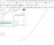
Once the ath.exe command completes, the dimensions are very close to the physical wave-guide. Unfortunately, when I execute the script, the ABCE Drawing tab displays a wave-guide with a "spider-web" across its mouth. Please, see the picture.
Despite cross-referencing the script against both demo1C.cfg and demo8C.cfg, I cannot find the problem. Thus, I was wondering if someone could review my (heavily commented) script and point me to the right direction.
Kindest regards,
M
Greetings all,
thanks to fluid and Marcel, I was able to acquire ABEC and successfully execute both the circular symmetry demos.
I than started to work on a script describing my wave-guide made ante-Ath(TM). The wave-guide is pure OS, hence OS.k = 1 in the script. It does fare slightly at the mouth, hence the remaining terms in the WAVE-GUIDE DEFINITIONS section.
Once the ath.exe command completes, the dimensions are very close to the physical wave-guide. Unfortunately, when I execute the script, the ABCE Drawing tab displays a wave-guide with a "spider-web" across its mouth. Please, see the picture.
Despite cross-referencing the script against both demo1C.cfg and demo8C.cfg, I cannot find the problem. Thus, I was wondering if someone could review my (heavily commented) script and point me to the right direction.
Kindest regards,
M
Attachments

You have a typo (missing 's') at this line:
Mesh.SubdomainSlices =
Unfortunately Ath doesn't let you know about that - it doesn't do any syntax checking yet. So what you see is the default subdomain interface, as if this line was not there. It shouldn't matter in theory but especially in the CircSym mode ABEC seems to give better results without it.
BTW, if you don't need the STL file (which is really not very useful here), you can switch if off (Output.STL = 0) and speed up the execution.
So you already have the physical waveguide and now you try to re-create that shape for a simulation? It would be very interesting to see both the measurement and the simulation results.Once the ath.exe command completes, the dimensions are very close to the physical wave-guide.
It's a pity I can't say that yet. I still need to do all the measurements but as I said, the prints are actually far from well damped and it seems that this technlogy is not well suited for that - it makes very rigid and somewhat ringing structrures. The final epoxy coating makes only a thin crust, probably not making much difference (my guess). I believe that casting would be the way to go - probably with what you suggest.... What Marcel is doing is the way to go.
Another thing is that it's probably a lot easier to damp the waveguide when clamped along the mouth (i.e. in a baffle) than the free standing one with its open end.
Last edited:
- Home
- Loudspeakers
- Multi-Way
- Acoustic Horn Design – The Easy Way (Ath4)