Hi Guys,
Me again, I find when I bias the boards on my aleph j the left board doesn't seem to be able to hold bias as high as the right board. On the right I can set the bias and it stays where I set it, on the left it goes up and then immediately starts to go down again. Any advice?
Also maybe I missed something but when I attached the binding posts they're incredibly loose and wiggly no matter what I try to do. Any advice would be appreciated. The amp still sounds fantastic but I want it to be the best it can be.
I figured out the bias problem. The way I attached the mosfets made them come loose. I blew the two amp fuse unfortunately while switching the amp on and off too fast. Going to the hardware store to get some replacement parts. I'll send photos of the speaker terminals in a few hours.
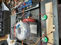
Unbolt the transformer and lift it as far away from the rest of the circuitry as possible.
Unbolted and set on top of plastic container. No change but was hoping. so. See picture
Attachments
For the 4u case the optimal bias value is .400 right? .450 is only if you have the 5u chassis, right?
Also with the speaker terminals, I have the notch in the slot in the chassis but the second washer on the inside doesn't have another slot to allow me to tighten it fully. There's still a gap when tightened all the way. Is there something I'm missing?
Also with the speaker terminals, I have the notch in the slot in the chassis but the second washer on the inside doesn't have another slot to allow me to tighten it fully. There's still a gap when tightened all the way. Is there something I'm missing?
Attachments
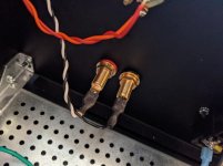
Nevermind about the speaker terminals. I read in another thread about the issue and how to fix it. Just have to buy some nylon washers and file them down somehow.
Unbolted and set on top of plastic container. No change but was hoping. so. See picture
I have an Antek AS 22-24 that has a purple ground wire coming out of the x-former. This x-former puts out 24VAC instead of 18VAC. Could I swap out and not destroy anything? The bias is already set lower to 250mV. Just want to sub out for troubleshooting the 120hz tone on the speakers. Thanks for any input.
I have an Antek AS 22-24 that has a purple ground wire coming out of the x-former. This x-former puts out 24VAC instead of 18VAC. Could I swap out and not destroy anything? The bias is already set lower to 250mV. Just want to sub out for troubleshooting the 120hz tone on the speakers. Thanks for any input.
See if you can neaten up the wiring.... by doing so, the issue may disappear 🙂.
If it does not, at least we'll be able to trace the wiring and make some sense of it...
Check the photo I attached. The mains wiring and the CL-60 are all soldered to the IEC filter block lugs. This will dramatically reduce the mains wiring length to approximately 13cm (5 inches max) in total.
The secondary wiring is twisted and tucked underneath the transformer metal plate and power supply PCB, and then fed to the PCB from underneath, and then sodered.
The power supply PCB is positioned in such way, to minimise the length of the DC wiring as well.
The above will give you the best performance and a very neat look.
Attachments

Last edited:
I put wires behind both boards trying to have less exposure (thinking of neatness at the time).
Will move some wires running under power/cap supply board. I think will take out from behind and try a minimalist approach and the picture you show is "show piece". I may move x-former to the rear and get rid of everything for space to do that.
Yes wiring is a mess while trying to trouble shoot. Thanks for reply and thanks to 6L6 also for the help. Will hopefully give an update next week. Cross fingers...........
cleaned up wiring, temp moved x-former to troublshoot.
Well no luck with moving the x-former and cleaning up the wiring. I may end up buying another x-former to see if it will fix this. The only reason I bought this one was they were out of the lower volt amp one specified in the build thread.
Thanks for the input. May put aside again for awhile to clear the mind..😕
If you order a new one, get the AS- series, as they have the shield.
AS-3218, AS-3220, AS-4218, AS-4220 are all currently in stock.
AS-3218, AS-3220, AS-4218, AS-4220 are all currently in stock.
Well no luck with moving the x-former and cleaning up the wiring. I may end up buying another x-former to see if it will fix this. The only reason I bought this one was they were out of the lower volt amp one specified in the build thread.
Thanks for the input. May put aside again for awhile to clear the mind..😕
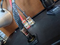
Are your blue/green wires from the trans. a matched pair. I would either twist or make them as short as possible
All done
At last after months of lurking the newbie guide with its Mouser shopping cart was all I needed to get nudged to the starting line...
Still there’s a slight hum when I hold my ear near the speaker. When the source isn’t plugged in I notice the buzz is louder when I touch the input lines. But when connected no amount of jiggling things around seems to make a difference. It’s a quiet hum- not perceptible when in use. But it’s def not dead quiet.
I ran the AC lines underneath the board. Rotating the transformer doesn’t seem to make a difference. As for options I followed those indicated in the newbie guide which I think is based in 6L6’s build guide.
Any thoughts for this newbie welcome.
Last edited:
Quiet is relative. It depends on the speaker sensitivity. If you have speakers that are not very sensitive, a noisy amplifier may seem quiet. However the best approach is to have your amplifier as quiet as possible so that if you have highly sensitive speakers, your amplifier appears quiet.
Here is something by diyAudio member Bonsai:
http://hifisonix.com/wordpress/wp-content/uploads/2019/02/Ground-Loops.pdf
I highly recommend following his advice and recommendations. I do and my amplifiers are quiet enough for my 103 dB speakers.
I see that that you have done a good job of twisting some of the wires in your amplifier. However, your V+, V-, and Ground wires from your power supply board to the amplifier boards are not twisted at all. The three wires to each amplifier board should be tightly twisted too.
If you look at Bonsai's recommendation for the ground point from the power supply, you will see that he recommends taking the ground from a location that is centred between the V+ and V- capacitors. Unfortunately the diyAudio power supply board makes it easy for builders to not do this. I have marked up your photo to show how this can be done. Instead of taking the ground off the board as you have done, take the grounds from the board where I have shown by soldering the ground wires to the board. Also add two more wires to join the grounds from the two sides of the board to better unify the ground.
The terminal block with AC wires is also quite close to the left channel circuit board. Moving it closer to the chassis centre line would probably be helpful. You can move the left rectifier block if needed to provide a bit more room.
One final suggestion is to rotate your power transformer so that the wire exit and entry points are at 12 o'clock and 6 o'clock. Those are leakage points and it is best if they do not point toward the amplifier circuits.
Attachments

First - still a self-admitted noob, so...
The first thing you could try is to be sure that all your audio GND points read a few ohms of resistance between the terminal and the chassis to be sure you don't have any accidental contact. Both speakers and both inputs. If you see anything amiss, check that all your washers etc. are in place.
I've read all the articles that have been recommended related to ground loops etc. I still don't know "what's best". What I can say is what's worked well for me, but I don't know why.
I ran my speaker returns to the PSU GND for more of a "star ground" configuration. At least that's what I think it's called. Running the signal and return line closest to the same point and in parallel with each other is purportedly "better", and is the way you have it.
However, that reduced hum/hiss for me in my Aleph J and a few other amps. I am not sure if that will work for you, but it may be worth a shot. Two wires and a few minutes to check may be worth the effort.
Other than that, even small changes in wire routing etc., made some minor changes for me. I used a pair of el-cheapo earbuds to listen for differences in noise as I moved things around, twisted things etc. etc. Keeping all AC as far away from my amp boards as practical made a difference. Also, rotating my transformer made a difference even when vertically mounted and on amps that did not have the signal transformers. They all added up to make some small differences.
The other thing that made a small difference in my builds was using a choke around my transformer primaries. I tried putting them around the mains directly, primaries, and secondaries. Primaries worked best for me, but YMMV. Again, I think I understand the basic mechanism for how they work, but I'm not sure why they worked where they worked best for me or the "optimum" place to put them.
I got these after a kind person recommended them.
https://www.amazon.com/gp/product/B01E5E5IY4/ref=ppx_yo_dt_b_search_asin_title?ie=UTF8&psc=1
BTW - I love your front panel!!! 🙂
Edited to add - I could have saved a bunch of time by just waiting for Ben 😀 Clearly, I type too slowly.
Last edited:
Are your blue/green wires from the trans. a matched pair. I would either twist or make them as short as possible
Yes they are a matched pair. If I ohm across a green to blue secondary wire out of circuit I get about .2 ohms. Read across green to other blue wire get Open reading so know the pairs are matched.
New transformer is on its way. Will try that and after seeing star grounding on some of the builds will work that route also. I have LED's on long leads and wondering if they are part of problem also. May take them out temporally also. Going to change transformer first then get into other troubleshooting. Thanks for suggestion.
But saw picture of another I thought F5 build not aleph build that had no purple ground wire coming out of the transformer and his was quiet. Wish I had that luck.
And take every precaution possible. Coax on the outputs. I don't know it it makes a difference but, the shielding can't hurt.
And when twisting wires. Don't just wrap one around the other. Have your wife do it, your sister or your girlfriend. Better yet, use a drill and don't get carried away. You only need so many wraps per inch.
And another note. All my tube amps can't compete. There on the shelf gathering dust.
And when twisting wires. Don't just wrap one around the other. Have your wife do it, your sister or your girlfriend. Better yet, use a drill and don't get carried away. You only need so many wraps per inch.
And another note. All my tube amps can't compete. There on the shelf gathering dust.
- Home
- Amplifiers
- Pass Labs
- Aleph J build guide for noobs