Maybe at the throat a bit just to cover the driver (if the screen is to be cut out), I don't know, definitely not filling the whole waveguide. The reason I want to make the waveguide transparent is to make the whole appearance little less prominent - that would hardly happen if filled with foam.@ Mabat
Are you planning on filling these waveguides with 30ppi foam or are you doing without? Thanks.
... Why would you make a separate waveguide if this can be made into a point source? The round-over can be incorporated into the baffle design so that the cone-to-baffle transition follows your model.
My concept is a combination of Genelec SAM baffle (8361A - Genelec.com) and Tannoy concentric, incorporating your advanced horn profile. Seems like a no brainer but I must be missing something.
Are you able to actually make it? Seems like a task of a completely different level of complexity to me.
Were the sims of this wg posted previously?
What are the dimensions?
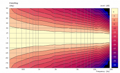
No, I don't think they were. They are around 500 x 200 mm. This is the polar map and all I'll show. To stay competitive I'll have to come up with more compelling and mysterious stories than a bunch of data 🙂
Attachments
Last edited:
referring to post #3842
....My concept is a combination of Genelec SAM baffle (8361A - Genelec.com) and Tannoy concentric, incorporating your advanced horn profile. Seems like a no brainer but I must be missing something.
Can you please try to draw one - it seems interesting!
//
BTW, I tried to simulate a throat extension plug (bridging over the driver's conical exit section) for FANE CD131, which is quite a nice 1" driver. It has a 3-slot phase plug ending at ⌀16 mm and 30° conical exit. Extending the waveguide profile down to the phase plug ending, these are the results for a ⌀320 x 120 mm free standing waveguide based on the latest advancements:
Attachments
Last edited:
Sika makes a pretty extensive range of resins. Some specifically for machined molds. Advanced Resins
I have a question regarding dome tweeters vs compression drivers in waveguides. I have problems getting a smooth response >10kHz when using domes as a sources. The larger the dome (and throat diameter) the lower in frequency the problem arises.
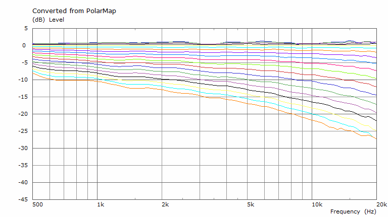
As an example this is the response from a small 150mm diameter waveguide with a flat source moving axially (1" throat diameter):

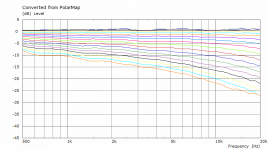
And this is the same waveguide with a tiny dome source instead (still 1" throat):

Is this a problem in reality? What are the pros of using a dome tweeter instead of a compression driver in general? (after all there exists alot of waveguide loaded dome tweeters)
As an example this is the response from a small 150mm diameter waveguide with a flat source moving axially (1" throat diameter):
And this is the same waveguide with a tiny dome source instead (still 1" throat):
Is this a problem in reality? What are the pros of using a dome tweeter instead of a compression driver in general? (after all there exists alot of waveguide loaded dome tweeters)
I would suggest at those frequencies the compression driver is always going to win out, but direct radiators are so much cheaper.
I wound up using the Tymphany NE19 VTS for many of my waveguide projects, largely for the reasons that you saw in your simulations. Basically there's a very good chance that the waveguide will have a dip in the response, when you use a tweeter that's larger than about 3/4"-5/8".
The devil is in the details, of course.
For instance, if you use a VERY shallow waveguide, like the ones used by Revel and Augerpro, you can get away with a tweeter that's larger.
But this leads to a catch-22:
1) A small diameter tweeter like the NE19VTS will work on very large waveguides, even seven or eight inches deep. Because of this, you can get *signficant* loading, all the way down to 500Hz or so. This allows you to run a tiny little dome tweeter down as low as 1khz!
2) On the flip side of things, you can put a larger tweeter on a very shallow waveguide and it might work. It's definitely trickier.
I wish there was an easy answer to this. As we speak, I have a SB26ADC tweeter on my desk, and a Fountek ribbon too. Because I can't decide what's best:
A beefy dome tweeter in a shallow waveguide?
Or a fragile tweeter that can take some abuse IF you put it in a large waveguide?
Indeed, this is not the compression driver that is more expensive... this is the horn.... (well but if one talk about Goto or Tad for instance that are expensive)
Pavillon polyurethane B&C Speakers ME464, pour moteur 1.4 pouce, facade 557 x 505 mm
Pavillon polyurethane B&C Speakers ME464, pour moteur 1.4 pouce, facade 557 x 505 mm
@Patrick Ok, it definitely seems trickier with larger domes.
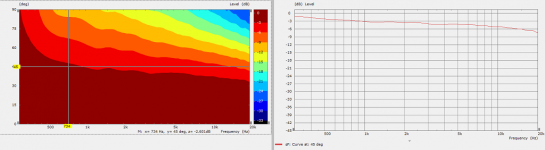
The above waveguide was the result of an first attempt at an optimization using an differential evolution algorithm. Basically it will fiddle around with the parameters in Mabats magic waveguide formula (creating combinations based on evolution), generate an ABEC project with the new parameters, simulate it and evaluate the results by calculate an directivity error. The objective of the algoritm is then to find the parameters that minimizes this error (0=perfect directivity)
I let it run over night and it produced something like 4000 simulations, here is a plot of all simulated combinations (you can see some trends of where the parameters are heading):

However when I tried doing the same thing but with a dome I got garbage since the algorithm did everything it could to reduce these 10kHz resonances, hence my questions above. Guess I have to refine my objective function for those cases
(Bonus animation of the profile for the first 100 iterations):

The above waveguide was the result of an first attempt at an optimization using an differential evolution algorithm. Basically it will fiddle around with the parameters in Mabats magic waveguide formula (creating combinations based on evolution), generate an ABEC project with the new parameters, simulate it and evaluate the results by calculate an directivity error. The objective of the algoritm is then to find the parameters that minimizes this error (0=perfect directivity)
I let it run over night and it produced something like 4000 simulations, here is a plot of all simulated combinations (you can see some trends of where the parameters are heading):
However when I tried doing the same thing but with a dome I got garbage since the algorithm did everything it could to reduce these 10kHz resonances, hence my questions above. Guess I have to refine my objective function for those cases
(Bonus animation of the profile for the first 100 iterations):
Amazing! That certainly sounds easier that doing it manually... ask me how I know... 
What did you use for scripting the simulations? I'm very curious to learn more about how you approached this!
What did you use for scripting the simulations? I'm very curious to learn more about how you approached this!
Wow, now this is something, finally someone has done it. I wish I knew how to do this - I considered it to be very difficult due to the interactive nature of ABEC and VACS. Do you use some sort of GUI automation to control the app? I used to use AutoIt for HolmImpulse automation, maybe that could work too.
I think you can safely make at least the 'q' fixed. What do you mean by "0=perfect directivity" - what's the formula for the error function?
I think you can safely make at least the 'q' fixed. What do you mean by "0=perfect directivity" - what's the formula for the error function?
Last edited:
BTW, I've been playing with free standing axisymmetric waveguides for a while and I can tell you these seem to be really the holy grail. I begin to think that making a rolled-back free standing waveguide is even better than making one built into a baffle as the rollback can be even smoother and the rest is not so important. Unfortunately the shape is not a simple closed formula anymore, which would complicate a similar optimization but maybe not that much after all.
BTW, I've been playing with free standing axisymmetric waveguides for a while and I can tell you these seem to be really the holy grail. I begin to think that making a rolled-back free standing waveguide is even better than making one built into a baffle as the rollback can be even smoother and the rest is not so important. Unfortunately the shape is not a simple closed formula anymore, which would complicate a similar optimization but maybe not that much after all.
From my limited attempts at putting together an optimization routine (in my case a manual experiment, in orreborre's case an algorithm - I think we all know which is better) I don't think the equation matters all that much.
As long as you can generate a set of points to define the nodes of the waveguide and the driver, ABEC can simulate it. I was using a Google Sheets script and copy-pasting the node definitions into a file attached to a generic ABEC project (which I believe I've shared in this thread). It seems the natural next step would be to write some sort of script to automatically generate nodes, update the ABEC project, run the simulation, evaluate the data, update the input parameters, and then loop.
The error function seems like the hardest and most interesting part of the problem now. Orreborre - please share more details on your approach!
As for the using the dome tweeters, I would also try a simple conical throat (the OS-SE formula can be altered for that easily, put k=0) or maybe a circular profile. These seemed to work pretty well when I tried.
Last edited:
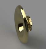
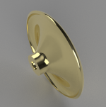
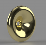
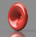
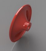
...finally, I can generate full solid bodies of the axisymmetric waveguides directly from the tool (via the Fusion 360 Python API). Can be exported as STL and sent to a 3D printer...
Attachments
Last edited:
BTW, I've been playing with free standing axisymmetric waveguides for a while and I can tell you these seem to be really the holy grail. I begin to think that making a rolled-back free standing waveguide is even better than making one built into a baffle as the rollback can be even smoother and the rest is not so important. Unfortunately the shape is not a simple closed formula anymore, which would complicate a similar optimization but maybe not that much after all.
Did you consider how the speaker system with free standing horn will work diffraction and polar response wise? Center to center spacing will be rather much with free standing waveguide with large rollback and a woofer in a separate cabinet.
Earlier I asked if it was possible to simulate taps in the horn wall, as in multiple entry horn. Multiple entry horn is the only way to get woofer close enough for smooth vertical polar response and get the speaker system close to point source. Especially with the large horn mouth rollback c-2-c will be more than one wavelength at crossover.
It would be interesting to see a simulation how much a tap affects the otherwise almost perfect performance of the horn, if it was easy to simulate, somehow 🙂 To me a holy grail speaker system has to be a multiple entry horn, no other way really. What is your view on this?
Last edited:
That's the best part -Did you consider how the speaker system with free standing horn will work diffraction and polar response wise? Center to center spacing will be rather much with free standing waveguide with large rollback and a woofer in a separate cabinet.
1) diffraction is not an issue with a proper rollback. I had my doubts at first but it does come out really well. The rollback effectively shadows everything behind the waveguide. For the woofer the wavelengths involved are also quite large so that the waveguide body itself doesn't present a major obstacle either. This was both simulated and measured.
2) I was surprised as well how small can a properly rolled-back waveguide actually be. It's not any bigger than a flush mounted one, if not actually smaller, with the polar response at least as good, if not better.
I don't think that's necessarily true. Certainly not with the waveguides as I do it.Especially with the large horn mouth rollback c-2-c will be more than one wavelength at crossover.
Well, you just have to pick your poison, I guess. I prefer maximizing the performace of a single entry waveguide and living with some vertical lobes at the crossover as the effect of this lobing can be really small in the end (it can have no effect on power response if done properly). I believe that especially with the larger waveguides and drivers that can be used low this doesn't present a real problem. The diffraction inside the waveguide would be. That's why I try to avoid that as much as possible.
- Home
- Loudspeakers
- Multi-Way
- Acoustic Horn Design – The Easy Way (Ath4)