Amazing! That certainly sounds easier that doing it manually... ask me how I know...
What did you use for scripting the simulations? I'm very curious to learn more about how you approached this!

I used python, for the optimization part I used the scipy module and for the GUI automatization I used the pywinauto module
Wow, now this is something, finally someone has done it. I wish I knew how to do this - I considered it to be very difficult due to the interactive nature of ABEC and VACS. Do you use some sort of GUI automation to control the app? I used to use AutoIt for HolmImpulse automation, maybe that could work too.
I think you can safely make at least the 'q' fixed. What do you mean by "0=perfect directivity" - what's the formula for the error function?
Yes I use GUI automatization, it works but I would definitely avoid it if I knew how to. I think most part of the optimization time is spent with GUI interactions.
...
The error function seems like the hardest and most interesting part of the problem now. Orreborre - please share more details on your approach!
I was hoping someone would be interested in this, as I would like to have some input in this part. After all this will set the quality of the results
So when I said Error = 0 = perfect directivity, I don't mean it as an absolute truth, it is just according to my half-assed attempt at the objective function which looks like this
For each off axis response in a specified frequency range:
1. Normalize the response (in this case it is to the on axis response)
2. Calculate the slope between each simulated frequency step. We now have an array with slopes. If they are all 0 we have a response that looks the same in shape as the on axis response (but can be of an arbitrary magnitude)
3. Then somehow we want to prefer a constant slope (beaming I think it is called) to a ragged or irregular response, so we calculate a new array as slope_corrected = slope - k*mean(slope). For k=1 and with a constant slope you would then end up with slope_corrected as an array of 0. This means that a beaming solution would be considered as good as a constant directivity solution. So k could be called beaming allowance factor (should be between 0-1)
4. Finally calculate the RMS error of the "slope_corrected" array
Hope you understand. I'd be very interested to hear if anyone has some clever solution here
As for the using the dome tweeters, I would also try a simple conical throat (the OS-SE formula can be altered for that easily, put k=0) or maybe a circular profile. These seemed to work pretty well when I tried.
That was actually the reason I included the k parameter, I was hoping to see it was moving towards 0 with the dome simulations. But I think all 10kHz resonances destroyed the convergence there
mabat, so horn with rollback is not much bigger than one without, with comparable performance other than what the better mouth termination provides you say? The #3792 measurements look really good, polars hold well below 1khz. 10" wavelength would be ~1350hz. One would still want to crossover to a (10") woofer around that 1350Hz for smooth transition, no? Which r to use for calculating ka? Just trying to figure out whats going on 😀
Just see the real measurements of such a waveguide: #3792
You hadn't seen anything like that before 🙂
And this was about 10" in diameter (!).
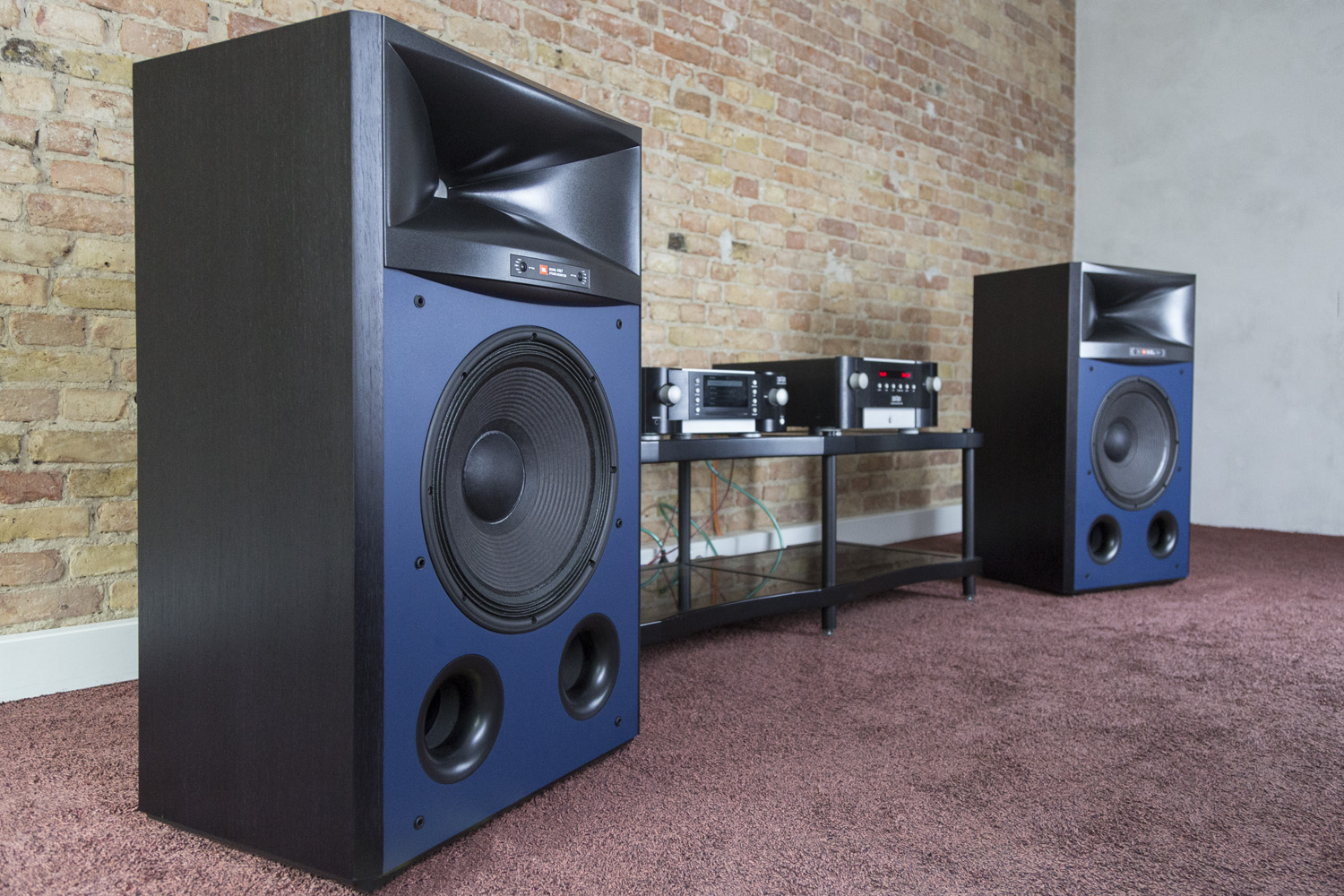
Two and a half years ago, I had the opportunity to listen to JBL's best speakers back-to-back with mid-range speakers from Revel, along with Revel's top of the line.
All three lines are very different:
* The JBLs were big ugly boxes with a compression driver
* The mid-range from Revel were elegant square boxes
* and the top of Revel's line are rounded off like a jelly bean
That experience really opened my eyes and spawned many threads on this forum. I realized that you can get a waveguide-like effect from simply rounding over the face of the cabinet. I believe the cabinet of the Revel is as important to the imaging of the speaker as the crossover and the drivers are.
big ugly box from JBL

an elegant square box from the mid-range of Revel's line
An externally hosted image should be here but it was not working when we last tested it.
and the 'jelly beans' that occupy the top of Revel's line
Last edited:
I'd say that for a similar performace a free standing WG would be smaller than a flush mounted one in a rectangular box. I now believe it's because the rollback is really the smoothest termination possible, without any contour curvature discontinuity. You simply won't achieve that with a rectangular box, no matter how rounded the edges.mabat, so horn with rollback is not much bigger than one without, with comparable performance other than what the better mouth termination provides you say?
For a particular DI curve it all depends on the driver, i.e. how low it can be used. I don't see a reason why a driver capable of 800 Hz in a home setup (a lot of 1" drivers can do that) couldn't be crossed over to an 8" - 9" woofer with such a waveguide. In fact, the particular waveguide shown is probably still unnecessarily big for that (i.e. for a 800 Hz crossover). It would definitely work pretty well.The #3792 measurements look really good, polars hold well below 1khz. 10" wavelength would be ~1350hz. One would still want to crossover to a (10") woofer around that 1350Hz for smooth transition, no?
Last edited:
I think Pet007 is testing (and listening to) the following (kind of random) combination right now -
Fountek FW168 (6.5") + B&C DE502 in the free standing waveguide shown above:

Fountek FW168 (6.5") + B&C DE502 in the free standing waveguide shown above:
Attachments
Last edited:
Way to go and do please post the winner!
//
//
@Patrick Ok, it definitely seems trickier with larger domes.
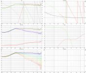
The above waveguide was the result of an first attempt at an optimization using an differential evolution algorithm. Basically it will fiddle around with the parameters in Mabats magic waveguide formula (creating combinations based on evolution), generate an ABEC project with the new parameters, simulate it and evaluate the results by calculate an directivity error. The objective of the algoritm is then to find the parameters that minimizes this error (0=perfect directivity)
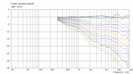
I let it run over night and it produced something like 4000 simulations, here is a plot of all simulated combinations (you can see some trends of where the parameters are heading):
View attachment 892593
However when I tried doing the same thing but with a dome I got garbage since the algorithm did everything it could to reduce these 10kHz resonances, hence my questions above. Guess I have to refine my objective function for those cases
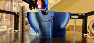
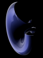
(Bonus animation of the profile for the first 100 iterations):
View attachment 892599

Bldy cool! In a real realisation, would one stuff the backside of the rollback with something. Foam.. etc...??
//
//
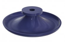
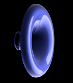
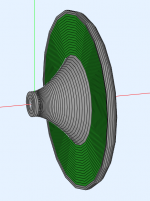
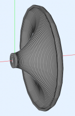
Axisymmetric free-standing waveguide for B&C DE7 - take this one as a promotion 🙂 ...
Fusion 360 public link (3D view): DE7_promo
Last edited:
I have no idea.In a real realisation, would one stuff the backside of the rollback with something. Foam.. etc...??
Promotion. Should I understand it that you plan to sell your designs, make custom ones or even sell ready made horns? That would be really cool! I'd definitely buy some🙂
Well, at least I could try this -I have no idea.In a real realisation, would one stuff the backside of the rollback with something. Foam.. etc...??
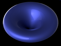
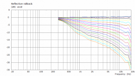
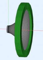
A sample 10" waveguide:
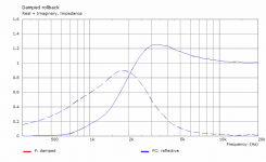
Rollback covered by a fully absorbing boundary element (green):
If carefully examined one next to each other, there's a slight difference below 2 kHz (not necessarily for the better). Of course the question is how well is this simple test close to the real thing, I don't know.
Attachments

Last edited:
Why "surprising"? A perfect absorber would also be a near perfect reflector, which is not what you want. You want no reflections at the mouth, hence as gradual a termination as possible is going to work best, whether or not it is an absorber or a flare.
- Home
- Loudspeakers
- Multi-Way
- Acoustic Horn Design – The Easy Way (Ath4)