You don't need to connect the circuit 0V to the case. You should connect the XLR pin 1's to the case only (but Hans will surely chime in here ;-).
The big advantage from differential connections is that you need no ground connection anywhere. Removing that case connection may improve things considerably, but no guarantee as a lot of other factors are unknown (to us).
Jan
The big advantage from differential connections is that you need no ground connection anywhere. Removing that case connection may improve things considerably, but no guarantee as a lot of other factors are unknown (to us).
Jan
So there is a DA connected ti’s input.
What is this DA doing, is it producing noise or whatever, and what is the sensitivity of the AD ?
In the 0dB position, the preamp is producing ca 12nV/rtHz which means ca 2uV for the 50Khz BW you used.
Is your AD capable of that ?
The other thing is that I see the LF noise rise by 40dB or a factor 100.
I find that very hard to understand.
What do you read when the DA is directly connected to the AD without and with telephone ?
Hans
The DA might produce a test tone to measure distortion etc, but in the measurement I have shown it does not do anything specific besides being connected, having an output impedance of 200R. This is kind of a real-world situation: a device connected to a preamp, which is connected to an AD. What you see in the graph I posted is DA->preamp->AD without phone (in black) and DA->preamp->AD with phone (in red). So the noise contribution from the 200R + whatever it produces on top of this there in both cases. Don't worry about absolute values. I can measure the DA/AD loop tomorrow, but IIRC the phone does not have a similar effect in this setting.
You don't need to connect the circuit 0V to the case. You should connect the XLR pin 1's to the case only (but Hans will surely chime in here ;-).
The big advantage from differential connections is that you need no ground connection anywhere. Removing that case connection may improve things considerably, but no guarantee as a lot of other factors are unknown (to us).
Jan
I meant the 0V from the -19V -- 0V -- +19V power supply. It is connected to the ground plane, which is connected to the chassis at the XLR connectors. It probably just goes to the center tap of the transformer.
I think by construction each XLR pin 1 is also first connected to the ground plane and then to the chassis via the screws, no?
A DA doing nothing is not possible because the least it produces at every clock cycle is dither with an rms value of 1/3Q.
So try to remove the DA and replace it with a 200R at the input between pin 2 and 3 or even by shortening these two pins.
Even then, I suppose your AD will have a hard time to measure the noise.
So my question is again,
How many bits has your AD and what is the maximum rms voltage it can convert before clipping.
Suppose your AD has the highest possible dynamic range of 120dB and can convert 4Vrms max, then it cannot measure the 2uV from your preamp.
Hans
A DA doing nothing is not possible because the least it produces at every clock cycle is dither with an rms value of 1/3Q.
So try to remove the DA and replace it with a 200R at the input between pin 2 and 3 or even by shortening these two pins.
Even then, I suppose your AD will have a hard time to measure the noise.
So my question is again,
How many bits has your AD and what is the maximum rms voltage it can convert before clipping.
Suppose your AD has the highest possible dynamic range of 120dB and can convert 4Vrms max, then it cannot measure the 2uV from your preamp.
Hans
Ok, what you are saying is that with my measurement setup I cannot possibly measure the noise of the preamp. You are of course correct.
What I am actually trying to measure is: "Does the preamp reject interference from my phone?". If I put the phone next to the AD/DA there is no effect whether the DA connected to preamp or not. If you see a more sensible way to do this test (without sending the preamp to a proper EMI testing lab), I'd be very interested. If not it would be great if you could put your phone next to your preamp to see whether it rejects the interference or not. This would give me a hint whether it's my implementation or the design that is causing the behavior you see in the graph I posted.
I’ll try to find some time to do a measurement.
One other question before that, was your phone idling or were you making a call to the phone while measuring ?
Hans
One other question before that, was your phone idling or were you making a call to the phone while measuring ?
Hans
I’ll try to find some time to do a measurement.
One other question before that, was your phone idling or were you making a call to the phone while measuring ?
Hans
Great, thank you! I was making a call over LTE to generate some interference while I put the phone on the preamp.
Result is even better as expected.
Two files where recorded with the preamp at 0dB and with open input.
The iPhone was situated as close as possible to the open input.
Image at the left is with iPhone idling and to the right with the iPhone calling and sorry, there is no difference.
Not shown here is the other channel from my A/D as a reference to be sure that the recorded BPBP noise is well above the A/D own noise.
For some reason Audacity could not switch my A/D to a higher sampling frequency this time, but for the purpose of this test I paid no further attention.
Hans
Attachments

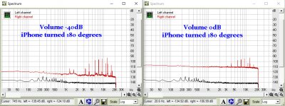
I did another test after having turned the iPhone 180 degrees, possibly leading to a closer position of the transmitter to the input.
And indeed, I could now see signs of EMF in the spectrum.
But when turning the volume down to -40dB, the EMF peaks stayed exactly the same, telling that this unwanted signal was not entered through the BPBP input but was picked up by the output cabling.
You can also see in black the spectrum of the A/D own noise as a prove that the red noise spectrum is indeed from the BPBP.
So this is it, I think the BPBP is not to blame for being extremely sensitive to EMF pick-up from a phone.
Hans
Attachments
I did another test after having turned the iPhone 180 degrees, possibly leading to a closer position of the transmitter to the input.
And indeed, I could now see signs of EMF in the spectrum.
But when turning the volume down to -40dB, the EMF peaks stayed exactly the same, telling that this unwanted signal was not entered through the BPBP input but was picked up by the output cabling.
You can also see in black the spectrum of the A/D own noise as a prove that the red noise spectrum is indeed from the BPBP.
So this is it, I think the BPBP is not to blame for being extremely sensitive to EMF pick-up from a phone.
Thank you for your measurements, this is very helpful! I am wondering why we see these spikes in the audio range, though. I was thinking the EMI somehow gets into the output stage of the BPBP and causes trouble.
Last edited:
Recorder,
I saw your earlier questions.
1) my supply is in a different box, almost behaving like a battery.
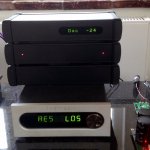
2) the preamp is in a metal box, see picture.
Top preamp, middle power supply and bottom phono preamp.
3) the supply needed for the display and for the volume relais is completely isolated from the preamp supply.
Hans
I saw your earlier questions.
1) my supply is in a different box, almost behaving like a battery.
2) the preamp is in a metal box, see picture.
Top preamp, middle power supply and bottom phono preamp.
3) the supply needed for the display and for the volume relais is completely isolated from the preamp supply.
Hans
Attachments
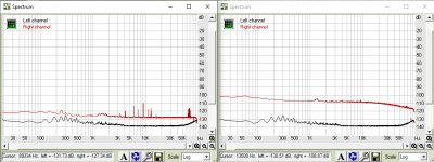
At last I got my AD working again at 192Khz instead of 44.1Khz and repeated the most noisy recordings that I made this morning.
As you can see, the peaks in the spectrum are not really at the spots that you saw earlier, but are artefacts of aliasing etc.
Images are again recorded at -40dB at the left and 0dB at the right in red.
Black is the A/D's own noise in the other channel.
But my conclusion is still the same that the phone's transmitting signal is not entering the input but is picked up by the output cabling and by the amplifier behind the BPBP that has no HF input filter at all like the BPBP has.
This amplifier was needed to lifting the noise signal, in this case by 27dB.
I see no reason to blame the BPBP's output circuitry.
Hans
Attachments
At last I got my AD working again at 192Khz instead of 44.1Khz and repeated the most noisy recordings that I made this morning.
As you can see, the peaks in the spectrum are not really at the spots that you saw earlier, but are artefacts of aliasing etc.
Images are again recorded at -40dB at the left and 0dB at the right in red.
Black is the A/D's own noise in the other channel.
But my conclusion is still the same that the phone's transmitting signal is not entering the input but is picked up by the output cabling and by the amplifier behind the BPBP that has no HF input filter at all like the BPBP has.
This amplifier was needed to lifting the noise signal, in this case by 27dB.
I see no reason to blame the BPBP's output circuitry.
Hans
Nicely built, Hans! The phono thing ruins the performance, though ;-) (just a joke, don't take it too serious)
How did you do your safety earth connection between the cases containing the power supply and the preamp?
I will try to replicate your measurements, mine were a little different because I was looking at the realtime analyzer in REW and the red points are the maximum in each frequency bucket. So far I can just say that if I connect the DA to the AD I cannot see any spikes, no matter where I place the phone. Only when I connect the preamp I can see something. It will take me a couple of days to find the time to make new measurements, but I will report back. Thanks again for your efforts!
The safety gnd was connected to the power supply box.
From this box +/-18Volt twisted lines went to the BPBP and the Phono preamp.
The zero volt lines are connected to the casing of these two boxes.
Hans
From this box +/-18Volt twisted lines went to the BPBP and the Phono preamp.
The zero volt lines are connected to the casing of these two boxes.
Hans
I see, thanks for elaborating. I guess you don't need to connect the preamps (phono and BPBP) to safety earth because +-18V is safe, right? Regarding the potential of the two preamp boxes do you mean that they are floating? Or is the secondary 0V line of the PSU connected to the PSU chassis? If the preamps are floating, may I ask why you prefer this solution as compared to having the 0V of the preamps at the same potential as the chassis of the PSU (i.e., safety earth)?
To start with, the safety ground or PE is connected to the chassis of the power supply box.
Of the dual internally generated +18V/0V/-18V for resp. Phono an BPBP, the 0Volt output lines are connected to this chassis.
The Phono and the BPBP are again connected to their resp. chassis via the screws of the XLR connectors that are connected to the gnd plane and thus via the 0Volt lines to the PE of the mains.
So all three chassis are firmly connected to the PE from the mains and nothing floats.
Hans
I will be using the Silent Switcher power supply. I have a ready made BPPBP with the optional regulators. Where exactly on the board would I connect the Silent Switcher?
They say here that you should not need the regulators. Connect the Silent Switcher where the regulators were.
Check the Regulator Data Sheet (HxR12) page 5. Pin 4 on both is output so this is where you would put the + and - outputs of the SlientSwitcher. The Ground is on different pins on HPR and HNR, and you should do a continuity check to see if they are tied together or not. You probably don't need to connect the ground from the SS to both Ground pins, but it would be good to check.
- Home
- Source & Line
- Analog Line Level
- BPPBP - Bruno Putzey's Purist Balanced Preamp (well a balanced volume control really)