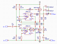
Built a circuit in Ltspice using your schematic and after changing a few values come up with Nelson's distortion and CLG values and frequency reponse almost exactly.You mention no R6,I left the circuit as you have it plus I added a gate stopper on the lower mosfet.Why do you say no R6?
Are the Alephs and the Mu' s not all twitters as far as the upper part delivers current gain?
:--))
:--))
Hi zchhopper,
very interesting and tough!
:--))
Your open loop gain is a bit high.
Mr.Generg,
Could you please explain how you did the OLG,I have a circuit here and have no clue how to do this measurement in LTspice.I have looked online and they insert a 0 volt source in the FB loop,i'm just not sure where it should go in the circuit I have (essentially the same one posted on this thread.)
Why is on the FW site the J2 marked as SE and the F8 as descendent as PP?
:--))
Probably because the F8 is setup for more push-pull operation than J2.
In fact we know this to be true due to lower feedback but higher damping factor.
A warning to ZM: cover your eyes. 
I about to present the circuit equations for the F8 and show how to derive resistor values if the parameters of the various FETs are known.
Interestingly, I found some values which give similar (simulation) results to the published F8 specs with 8R load but are much better at 4R.
I about to present the circuit equations for the F8 and show how to derive resistor values if the parameters of the various FETs are known.
Interestingly, I found some values which give similar (simulation) results to the published F8 specs with 8R load but are much better at 4R.
Boyz, F8 is still in production
some decency is expected - do what you wish out of public
make your own Babelfishes (unnecessary complicated iterations) in public
damn Greedy Boyz
some decency is expected - do what you wish out of public
make your own Babelfishes (unnecessary complicated iterations) in public
damn Greedy Boyz
I noodled on how to approach calculating the jumble of physics that balanced bias level and cancellation and transfer and . . ... I gave up 😕.
I know EUVL said in the J2 thread that if he added current sources in the input stage it would lower the distortion below production J2 levels, but that was not really the point of the excercise.
I cheated anyway . . . I'm sure not a novel solution, but satisfyingly novel to me. And the schematic now has sexier symmetry and dreamy (simulated) numbers at 1 watt while keeping dissipation at about 35W per mosfet.
It deviates a bunch from the F8 simplified schematic. If I find it sounds great and if anyone is interested I will open its own thread and stop polluting here.
Attachments
Boyz, F8 is still in production
some decency is expected - do what you wish out of public
make your own Babelfishes (unnecessary complicated iterations) in public
damn Greedy Boyz
Same thing happened with F7.
Not so cool.
Hi Oreo382,
Open this comment again
https://www.diyaudio.com/forums/pass-labs/358672-watt-f8-9.html#post6374021
Open the picture, you see in the upper line
V(out) divided by the difference of the ( V( at the node of J-Fet(s) input gates - V( at the node oft the J-Fet source point, where the feedback resistor ends)
This gives the OLG.
This can be done in a real circuit too, with high V(out) let us say 10V AC 1kHz and a DMM with very high input impedance.
:--))
The motivation of Nelson to publish any schematics of his is, I am sure, not only to encourage people to build amplifiers.
It is also about educating people on analogue circuitry and how they work.
So if someone were to take a generalised / simplified schematics in the public domain, and publish a mathematical analysis of it, I cannot see how that contradicts Nelson's motivations.
A generalised analysis says nothing about the actual amplifier design, including component values and choices, matching details, power supplies, etc.
What I personally find much more offensive is for those people who have access to the original product details to clone and sell copies of them in private.
That, to me, is 100% theft.
Only my personal view,
Patrick

Thank you! for your help.One point,when I measure my circuit I get about 15db? My CLG measures about 14db.Does this sound right?I see your OLG measurement was up to 75db,mine is ruler flat 15db.I took my measurements at the same points as you said.Hi Oreo382,
Open this comment again
https://www.diyaudio.com/forums/pass-labs/358672-watt-f8-9.html#post6374021
Open the picture, you see in the upper line
V(out) divided by the difference of the ( V( at the node of J-Fet(s) input gates - V( at the node oft the J-Fet source point, where the feedback resistor ends)
This gives the OLG.
This can be done in a real circuit too, with high V(out) let us say 10V AC 1kHz and a DMM with very high input impedance.
:--))
Now I see, so Nelson lets the genie out of the bottle and are job is to try and put the genie back.
Hi generg,Why is on the FW site the J2 marked as SE and the F8 as descendent as PP?
:--))
Hope that you and all are well and safe.
US 5,710,522; Nelson Pass inventor describes its inventive schematic [F8..]as push-pull.
Hi generg,
Hope that you and all are well and safe.
US 5,710,522; Nelson Pass inventor describes its
inventive schematic [F8..]as push-pull.
That is the Aleph circuit, not a mu follower. Nowhere in the text of the patent do I see the words "push-pull", but the circuit behavior upper FET is obviously actively contributing to the output.
Why is on the FW site the J2 marked as SE and the F8 as descendent as PP?
:--))
Referring to zchopper's schematic in post #85 - assuming it's a realistic representation First Watt F8 Isn't 100% modulation applied to the upper FET via C5? I believe the Aleph modulation is somewhere between 50% & 75% depending how the pot is set.
A modulated current source, as in the Aleph, J2 or MCS Borbely, is IMHO not the same as a conventional push-pull, e.g. as in Kaneda or JLH Class A.
The modulated current source is driven by output current of the driver device (e.g. the lower Semisouth in the J2), and hence sees the distortion of the latter.
This is not the case for a phase splitter or diff pair driven push-pull.
The resulting distortion spectrum is therefore different.
The Borbely EB602-200 Revisited
The Class-A Amplifier Site
_UHC_MOS-FET_Power_Amp
Cheers,
Patrick
- Home
- Amplifiers
- Pass Labs
- First Watt F8