DIYers OCD??? Never!!!
All I know is that the F8 prototype at 2019 BAF was AWESOME! But then again, so is my J2.
😀
All I know is that the F8 prototype at 2019 BAF was AWESOME! But then again, so is my J2.
😀
I wonder if Papa will ever do a Firstwatt integrated. That would be bloody cool.
Actually it would probably be hot too. 😀
There doesn't seem to be enough attention on his front end products, which is a shame because they should be implemented to get the intended end result.
Actually it would probably be hot too. 😀
There doesn't seem to be enough attention on his front end products, which is a shame because they should be implemented to get the intended end result.
Yeah, that would be great. It would be cool to see a Wayne contribution to a FW integrated. Very possible that’s happened, but suppose I’m imagining a FW version of the INT-25 🙂
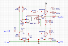
f8ish circuit with mosfet.
Having never strayed more than a few ohms away from schematics I've found on this site, I am quite proud of my effort here and wanted to share and ask a couple questions. I saw the simplified schematic of the F8 and got a wild hair. I was shooting for something that makes recognizable sound and ended up with something that blows my mind. It even does complex music well. And the louder I play it, the better it sounds. Could be I've never heard this much distortion and I love it 😛 The wife thinks it might sound better than my diy F5. Of course I think it sounds better than anything I've ever heard.
There are a couple things I haven't been able to fix and one bigger issue with the sound i'd like to get a handle on. Anything less than 1 ohm on the bottom fet and the bias starts running away. I know the drain resistor and network on divider on the gate of the jfet are out of whack, but this is where it sounds the best. Not sure if there is some other way I can tame the bottom fet.
Spice tells me the bottom fet should be pushing more watts than the top as I have it built, but its the top one's heatsink that gets really warm. Is that because the power from the bottom is being dissipated as sound and through the speaker?
There also seems to be a whole lot of bass. Could be what is called "bloom" or "bloat". . too much maybe? Not enough drive from the jfet, too much capacitance on the 150 mosfets? I have tried an entire range of feedback adjusting both resistors thinking maybe lower out impedence could help, but it doesn't sound as good and doesn't really help with the bass.
Anyway . . So So So Happy. Thanks Mr. Pass and everyone. DIYing my own has always been one of those pipedreams.
R6 shouldn't be there on the schematic. R5 is 183k to ground.
Attachments

IRFP140 or IRFP240 is probably a better fit here.
Well not necessarily better but maybe closer to Semisouth.
Well not necessarily better but maybe closer to Semisouth.
Try IRFP240 and bias it for 1.5A.
Make sure you are using either mica and goop or Keratherm pads, and you have the mosfets mounted tight with spring washers.
That should certainly make it thermally more stable as a first step.
You should be able to lower the resistance at that point.
Thinking R11 should maybe be smaller, maybe around 1k.
You don't have a gate stopper on Q2.
Last edited:
@zchopper
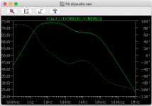
When I adjust lower OLG of about 50dB in Spice I get no more 0.012% but 0.12% distortion.
So it stays Nelson secret how he managed to get around 0.012% with the mentioned 10dB lower OLG than the J2.
I still try to solve this riddle....

and you are one step more forward than me, you already heard your tweaking......!
When I adjust lower OLG of about 50dB in Spice I get no more 0.012% but 0.12% distortion.
So it stays Nelson secret how he managed to get around 0.012% with the mentioned 10dB lower OLG than the J2.
I still try to solve this riddle....
and you are one step more forward than me, you already heard your tweaking......!
Nelson states in the F8 manual:
"As you compare the J2 and the F8, you will find quite a bit of similarity, but the
F8 is a modest improvement in several areas. In particular, the damping factor
and high frequency response are twice as good, and distortion numbers are
lower. I am pleased to note that this is achieved with 10 dB less open loop gain
on the circuit and 5 dB less feedback."
too much on my plate
besides, nothing to Babelfish there
on the other hand ...... plethora to Babelfish there .....
besides, nothing to Babelfish there
on the other hand ...... plethora to Babelfish there .....
Hahahahaha.
I am not in any hurry with this.
The thing that most attracts me is that I don't have too many matching 2sj74 parts left, this makes things far simpler.
I am not in any hurry with this.
The thing that most attracts me is that I don't have too many matching 2sj74 parts left, this makes things far simpler.
Q3 is hotter than Q2: What is the voltage at the source pin of Q3?Spice tells me the bottom fet should be pushing more watts than the top as I have it built, but its the top one's heatsink that gets really warm. Is that because the power from the bottom is being dissipated as sound and through the speaker?
Yes, the IRFP150s have a much higher input capacitance than the SemiSouths, which would explain some of the issue.There also seems to be a whole lot of bass. Could be what is called "bloom" or "bloat". . too much maybe? Not enough drive from the jfet, too much capacitance on the 150 mosfets?
Q3 is hotter than Q2: What is the voltage at the source pin of Q3?
The power supply is 50.2. Source of Q3 is 27. Drain of Q2 is 25.8.
Yes, the IRFP150s have a much higher input capacitance than the SemiSouths, which would explain some of the issue.
I'm a little limited in my stock of avail mosfets without pulling from already built. I'll order some. I have some IRFP044s. I'll try to see if there is a difference.
Try IRFP240 and bias it for 1.5A.
Make sure you are using either mica and goop or Keratherm pads, and you have the mosfets mounted tight with spring washers.
That should certainly make it thermally more stable as a first step.
You should be able to lower the resistance at that point.
Thinking R11 should maybe be smaller, maybe around 1k.
You don't have a gate stopper on Q2.
They're held down firmly with a crossbar over them on Aluminum Oxide with goop. It has worked for me so far and I value the re-usability. I have some mica somewhere in a drawer I can try.
R11 I found by listening. I have sat for several hours with a screwdriver on a pot starting at 150 and at least 3 times I've measured it has ended up about 2600.
Gatestopper ended up being bypassed because of a soldering error 😎
Attachments
- Home
- Amplifiers
- Pass Labs
- First Watt F8