I think that it will be less delta delay in relation to the isolated digital lines. Does not matter much about delay until it is "same" for all isolated lines. But unfortunately delay is not the same for different frequencies. For data and BCK of DSD will be the same but for MCK with higher F it will be more delay. That could be detected with a osciloscope.
This delata delay is data of interest. And maybe could be solved by cascading 2 inverters in MCK line? But I think that is delt delay between DATA and MCK isolated lines is small?
.
Somehow I preferred adum type of isolation them other types of "C" isolation elements and I think that You can use with 3.3V supply with a little decreased speed? Maybe there are option to use adum-s at 5V each side for hufher speed, because if You go with separate isolated box to dac anyway You will need diff. transmitter. And probably some of them are accepts 5V input?
The clock goes straight to the raw DSD valve DAC (shortest possible path for minimum jitter) and via an isolator to the Beagle Bone Black, while the data go from the Beagle Bone Black via an isolator to the flip-flops. That means there are two isolator delays and a Beagle Bone delay in the data path that are not in the clock path. So for the set-up time of the first flip-flops of the raw DSD valve DAC, it is the isolator delay rather than the delay matching that matters.
I actually drafted a lvds version, but it is a bit clunky. I am going to redo it and draft another version (AD4654/AD4655 for data and clock, regular Adum for mute and other slow lines) later today and tomorrow. I am reading and learning quite a bit about lvds last couple days. I found these newly released combined lvds isolator and sender/receiver. drum roll please .................. 4 ns typical propagation delay, 2.6 ps rms typical random jitter, rms, 90 ps typical peak-to-peak total jitter at 1.1 Gbps. They run on 2.5VDC.
Selection Table for Isolated LVDS | Parametric Search | Analog Devices
I think I can use a 2:2 differential clock multiplexer and feed one signal, all differential, from the DAC side, pass the cable, to BBB, and then convert to lvttl just before the BBB mck-in. The other signal goes from the multiplexer to a non-inverted schmitt-trigger and to a valve dac.
Last edited:
Hi Marcel, hoe gaat het ermee?
I'm still thinking of using a AK4137 or maybe CT7302 (supposed to be better?) to do the DSD processing for the valve DAC.
As the raw DSD PCB needs a clock input I assumed that could be taken off the AK4137 board, but is there some way to use your original tube oscillator circuit to generate the clock signal for the DAC?
...And maybe could be solved by cascading 2 inverters in MCK line
I made mistake sorry
should be in DATA lines (and in BCK line if used)
Reconstruction Filter PCBs and smd stencils are just leaving the fabricator. Main DAC PCB fabrication is at 78%.
Here is updated v0.2 of the thingy connecting a BBB to the Valve Dac. It has a separate PCB for the BBB side and one for the DAC side. For ease of referencing, I link to datasheets.
SN65LVDS1/SN65LVDS2
https://www.ti.com/lit/ds/symlink/sn65lvds2.pdf
ADN4654/ADN4655
https://www.analog.com/media/en/technical-documentation/data-sheets/ADN4654-4655-4656.pdf
ADuM130D
https://www.analog.com/media/en/technical-documentation/data-sheets/ADuM130D_130E_131D_131E.pdf
FIN1047M
https://www.onsemi.com/pub/Collateral/FIN1047-D.pdf
FIN1048M
https://www.onsemi.com/pub/Collateral/FIN1048-D.pdf
SN74LVC1G17
https://www.ti.com/lit/ds/symlink/sn74lvc1g17.pdf
SN74LVC1G125
https://www.ti.com/lit/ds/symlink/sn74lvc1g125.pdf
SN74LVC1G126
https://www.ti.com/lit/ds/symlink/sn74lvc1g126.pdf
Wuerth 7499151120
https://www.we-online.de/katalog/datasheet/7499151120.pdf
Please take a look and comment. Thanks.
Attachments
Last edited:
Hi Marcel, hoe gaat het ermee?
I'm still thinking of using a AK4137 or maybe CT7302 (supposed to be better?) to do the DSD processing for the valve DAC.
As the raw DSD PCB needs a clock input I assumed that could be taken off the AK4137 board, but is there some way to use your original tube oscillator circuit to generate the clock signal for the DAC?
The only way I see is rather cumbersome: you could download the KiCad database of the original valve DAC main board from the Linear Audio website, cut out the connectors for the FPGA board, the SRC4392 and the DIX4192, and put the AK4137 or CT7302 and whatever supporting circuitry it needs in the resulting hole. You then have to have your own custom main board manufactured, with a four-layer stack-up with a double prepreg layer of about 360 um total thickness (which is the standard four-layer stack-up for Eurocircuits and a special custom stack-up for most other PCB manufacturers). Using a clock from an AK4137 sounds easier and less expensive.
The CT7302 definitely has smaller passband ripples for the ASRC filters than the AK4137: +/- 0.0001 dB for the interpolation and +/- 0.0001 dB for the decimation filter of the CT7302 and +/- 0.01 dB for the sharp filter of the AK4137. The smaller the ripples, the smaller the level of the pre-echo. The AK4137 features optional apodizing filters, while the CT7302 does not.
I am actually not too sure about the terminations between LVDS drivers and the ethernet connectors. Do I need those 100 ohm resistors there? Also, ethernet connectors have 75 ohm resistors at center-tapped to shield. Will that affect the 100 ohm impedance?
I know that there are LVDS specific cables and connectors. Maybe I should use them instead.
I know that there are LVDS specific cables and connectors. Maybe I should use them instead.
Last edited:
I think those 100 ohm resistors should not be there. The LVDS driver datasheets show that they are meant to be used with only a termination at the load.
I also see two issues with the transformers. One is that the way the centre taps are connected drives some LVDS in- and outputs outside their recommended common-mode range, the other is that the DSD signals have far more low-frequency content than an Ethernet signal.
Regarding that second issue, Ethernet signals are designed to have very little spectral content at low frequencies, so they pass through transformers with a small magnetizing inductance unscathed. When you play a church organ recording with a 16 Hz pipe, the DSD audio signal will have a strong spectral component at 16 Hz that can't pass through an Ethernet transformer.
What will happen is that the low and high levels at the output of the Ethernet transformer will be skewed. For example, if during the peak of the church organ waveform 3/4 of the bits in the DSD signal are ones and 1/4 are zeros, the whole waveform will shift down such that the zeros are three times as far below zero as the ones are above it. During the negative peak of the church organ waveform, the whole waveform will shift up.
If the receivers are sensitive enough, which they should be, the data will still pass through, but the timing and the noise margins get modulated by the audio content of the DSD signal. For this reason, I would not use transformers at all.
I know that there are LVDS specific cables and connectors. Maybe I should use them instead.
Ethernet cables are also 100 ohm, so they should work well.
The cables to the U.FL connectors of the raw DSD valve DAC have to be driven by 3.3 V or 5 V CMOS outputs with series terminations. That is, R119 and R120 on the DAC side board should be 27 ohm or 33 ohm (so you get about 50 ohm including the output impedance of the logic gate) and R116 shouldn't be there. R114 and R115 should also be in series with the logic gates and have reduced values. As the CMOS outputs of the SN65LVDS2 are relatively weak, I would use 18 ohm here.
Will reduce values of R119 and R120. Instead of u.fl connectors and cable, I am thinking that it may be a good idea to have a pcb mounted 20 pin connector that plugs directly onto P13 of Valve Dac. The output of the three state buffers, and data lines will be less than 25mm from P13. Do you think that we can remove R114, R115 and R116 completely?
I found many 8P8C connectors on Digikey and Mouser. Much cheaper too, without transformers. I think using ethernet cables is a better idea than using specialized cables from vendors that want you to "ask for quote." Ethernet cables are very high quality and cheap.
I found many 8P8C connectors on Digikey and Mouser. Much cheaper too, without transformers. I think using ethernet cables is a better idea than using specialized cables from vendors that want you to "ask for quote." Ethernet cables are very high quality and cheap.
Last edited:
The disadvantage of P13 is that one clock line is right next to a DSD data line while the other clock line is even sandwiched between data lines. That's not the best pin-out when you want to keep the clocks clean, but it had to be that order to make it compatible with ppy's reclocker and with the Amanero (after removing the ground pins that shouldn't have been grounded). Then again, the effect can't be too bad, as Ray uses this connector and it doesn't seem to bother him.
If the connections are just a few centimetres, you can remove R114, R115 and R116.
If the connections are just a few centimetres, you can remove R114, R115 and R116.
...Then again, the effect can't be too bad, as Ray uses this connector and it doesn't seem to bother him.
I've been listening rather than tweaking of late and to be honest I haven't even thought about adjusting the clock pots as I've got it sounding fantastic so, no, I'm not aware of any issues and, to be frank, it's very difficult to imagine how the sound might be improved. I'm not saying it can't be improved, just that I find it so enthralling it's difficult to imagine it sounding better.
I think 1Vrms from the Lundahl Filter PCB is too low to be optimal without a pre-amp in my system. My current DAC has 2Vrms and it's OK.
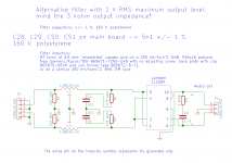
I promised to look into using the Lundahl transformer as a 1:2 step-up to get a 2 V RMS output level. This has some disadvantages:
1. The transformer distortion at very low audio frequencies increases. I estimate that it becomes 0.2 % at 20 Hz at the maximum scarlet book compliant signal level, it drops quickly at higher frequencies. Then again, when the alternative is to insert an extra valve stage, that will distort at all audio frequencies.
2. The output impedance increases from 750 ohm to 3 kohm, so you can only drive short cables and fairly high-ohmic inputs with it.
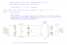
3. The impact of the transformer parasitics on the filter gets larger. I found I could minimize this effect by making use of the reciprocity of the filter and swapping it. The capacitors on the main board then become 5.1 nF instead of 15 nF. Even with the swapped topology, transformer winding capacitances make up most of the second filter capacitor when you use the transformer as a 1:2 step-up.
In fact swapping the filter to reduce the sensitivity to transformer parasitics is also useful when you use the Lundahl as a 1:1 transformer and accept a 1 V RMS level. See the attached schematics, and note the deliberately reduced value of C9.
Attachments
Last edited:
Please ignore the statement: "Even with the swapped topology, transformer winding capacitances make up most of the second filter capacitor when you use the transformer as a 1:2 step-up", as it is a mistake. About a third of the capacitance comes from the transformer, based on my estimates of the transformer parasitics.
I promised to look into using the Lundahl transformer as a 1:2 step-up to get a 2 V RMS output level.
Just to point out that Marcel's additional filter schematics are not the same as the one used for the GB filter PCBs. If anyone want's to use these new filters designs I'll happily make new versions of the filter PCB and provide a set of gerber files so a small batch of PCBs can be ordered.
Marcel, kind of you to investigate 1: 2 step-up.
I think I will start with the 1Vrms solution and see if it works.
I have now also examined the active crossover for my LX521 speakers. It looks like I could increase the gain there if it turns out to be needed.
Thanks!
Micke
I think I will start with the 1Vrms solution and see if it works.
I have now also examined the active crossover for my LX521 speakers. It looks like I could increase the gain there if it turns out to be needed.
Thanks!
Micke
- Home
- Source & Line
- Digital Line Level
- Valve DAC from Linear Audio volume 13