It is almost impossible to achieve complete symmetry. Although in this circuit it is necessary to select transistors and resistors in pairs.
Sure. However, the even harmonics should cancel out due the symmetry of the circuit. Why is this not the case here?
The complete identity of the shoulders is not only unrealistic. But it is not necessary.
It is more important that the non-identity is close. In pairs, in the channels.
As a result, we have less hassle. And a good spectrum. Identical in the channels.
Last edited:
Naaaah... Sure, the cancellation of the even order harmonics is not 100% perfect, but it should still work. The 2nd harmonic should be a lot lower.The complete identity of the shoulders is not only unrealistic. But it is not necessary.
It is more important that the non-identity is close. In pairs, in the channels.
As a result, we have less hassle. And a good spectrum. Identical in the channels.
Naaaah... Sure, the cancellation of the even order harmonics is not 100% perfect, but it should still work. The 2nd harmonic should be a lot lower.
Create problems for yourself. To fight them later? )))
When it is possible to do without them at once.
Ultra-low harmonic levels are not required at all.
Except for the "simulatormans".
Create problems for yourself. To fight them later? )))
When it is possible to do without them at once.
Ultra-low harmonic levels are not required at all.
Except for the "simulatormans".
I don't understand what you are saying about problems. Which problems?
I am simply trying to understand why the 2nd harmonic is so much higher than the 3rd.
As if everything has already been said about it. Why so.
And it's very good. Almost ideal.
Build for yourself. To make sure.
The design is not complicated.
And it's very good. Almost ideal.
Build for yourself. To make sure.
The design is not complicated.
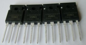
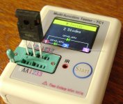
I finally got USCi. I measured them with a multimeter. The gate has a resistance greater than 2 mΩ. D-S shows resistance-full zero. Probably because SiC Normally-On Junction Gate Field-Effect Transistors. The Chinese device identified them as two diodes.🙂
Attachments
Last edited:
 Nice jfets jpatay! Curious to see what if any difference in circuit between UJ3N065025K3S. I’m waiting to order parts until my PCB’s arrive next week.
Hi, Jonathan!!! I have already turned on the amplifier on the USCi.
If the voltage across the USCi gates is 8.9 V, then the current is 140 mA. The frequency response is linear (0 dB) up to 400 kHz. Found two nuances. When all power supplies are turned on at once, a large inrush current is generated. We'll have to make the USCi power-on delay. And the USCi current increases slightly as it heats up, but I will still closely watch the current increase.
If the voltage across the USCi gates is 8.9 V, then the current is 140 mA. The frequency response is linear (0 dB) up to 400 kHz. Found two nuances. When all power supplies are turned on at once, a large inrush current is generated. We'll have to make the USCi power-on delay. And the USCi current increases slightly as it heats up, but I will still closely watch the current increase.
Last edited:
How long of a delay would be adequate? Would a soft start circuit or even the typical Pass solution of a CL-60 do the trick or is more delay needed?
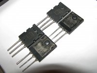
A good result was obtained with the 2SK1530.
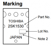
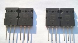
But now it will be difficult to find original ones. Here is a photo of the original 2SK1530.
There should be a dash where - Note 2 and JAPAN is slightly shifted to the left.
But now it will be difficult to find original ones. Here is a photo of the original 2SK1530.
There should be a dash where - Note 2 and JAPAN is slightly shifted to the left.
Attachments
Great to know what to look for on these. Are you still developing the USiC or is the Toshiba the better performer at this point?
Measured Rout on USCi - 1.4 ohms.
On Mosfet IRFP150N - 0.12 ohms.
Mosfet is better and does not need a power-on delay.
We are thinking of ordering a 2SK1530 here:
2SK1530-Y Toshiba | Интегральные микросхемы | UTSOURCE
On Mosfet IRFP150N - 0.12 ohms.
Mosfet is better and does not need a power-on delay.
We are thinking of ordering a 2SK1530 here:
2SK1530-Y Toshiba | Интегральные микросхемы | UTSOURCE
Wow, thanks for information about #137!
Does anybody knows honest source 2SK1530? Used, refurbished?
Does anybody knows honest source 2SK1530? Used, refurbished?
Would a soft start circuit or even the typical Pass solution of a CL-60 do the trick or is more delay needed?
For MOSFET, I solved the problem by setting a capacitance of 220 uF on the ADJ LM317 positive bus.
When turned on, the voltage at the gates increases smoothly from zero to 3.8 V.
On USCi, I couldn't do that.
Attachments
Well that is an easy fix for the MOSFET. Are you referring to the Toshiba 2SK1530 when you say MOSFET?
I am trying to find the combination for best sound now that I have boards in hand. I also have Vishay IRFP150PBF as well as Exicon ECX10N20-S.
Are all USiC off the table now? What about the UJ3N065025K3S? It appeared you had some success with that jfet earlier on. Did it also require the turn-on delay?
ECX10N20-S are good transistors for sound, but would it be better to put the IRFP150PBF first? Alexey Semin worked with UJ3N065025K3S.
They have a large capacity. Mosfet transistors IRFP264, IRFP150N and 2SK1530 have proven themselves well. But the 2SK1530 were the best. The circuit works better on MOSFET transistors.
They have a large capacity. Mosfet transistors IRFP264, IRFP150N and 2SK1530 have proven themselves well. But the 2SK1530 were the best. The circuit works better on MOSFET transistors.
- Home
- Amplifiers
- Solid State
- JFET-only Circlotrons without negative feedback