This is done to rev 2.0.52.0. I tried to make parsing according EASE's documentation found in www: V[mmm]H[ppp] where V[mmm]=meridians and H[ppp]=parallels.
My interpretation is that V[mmm] is orbit (phi in CLIO) and H[ppp] is off-axis (theta in CLIO). Few examples:
- V000H060 => Hor 60 in VCAD
- V000H300 or V180H060 => Hor -60 in VCAD
- V090H060 => Ver 60 in VCAD
- V270H060 or V090H300 => Ver -60 in VCAD
I'm not entirely sure that it's correct. Could you verify is this okay?
Hi Kimmo,
I just returned from holiday, thanks for making this option!
However, while checking it seems not to work as expected (getting the error: 91 rotated or illegal derctions not loaded), I have a link with some measurements in it, so maybe you could see on your system what goes wrong.
Ease Speakerlab format measurements.rar - Google Drive
Many thanks for the effort again!
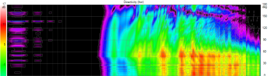
ps attached is a polar picture of speakerlab; the measurements should give these reults (hf horn, 80degrees opening angle)
Attachments
Last edited:
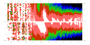
^Very sorry but the files and graph don't match imo. Filenames are V000H000 ...V000H180 which looks one side from main axis 0 deg to rear +180 deg in horizontal plane, but not the other i.e. negative angles. Graph shows half space from -90 deg thru axial 0 deg to +90 deg, but not rear sector at all. In addition, response in horizontal plane changes sharply in graph when angle sign changes from positive to negative. Typically that does not happen with any horn. All this assuming that V000H000 is main axis (0 deg hor & ver) and angle value after "H" is not divided by >1 or mirrored to other plane. Response file V000H046 or V000H048 has the highest magnitude.
So far I've just removed "-ref" and ".spk" from filename before angle parsing. Angle reading works okay, but something else might be needed. Official documentation with images could help.
So far I've just removed "-ref" and ".spk" from filename before angle parsing. Angle reading works okay, but something else might be needed. Official documentation with images could help.
Last edited:

Hi Kimmo,
thank you. its clear to me now.
But technically it does not make a difference, if i set up a delay (eg equals -10mm) or set up an z-Position of the the speaker of -10 mm? or does it make a difference in the calculation?
If you draw x and y on a paper, z is almost most often *into* the paper.
//
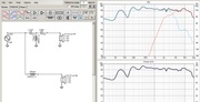
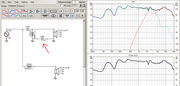
A big thanks to Kimmo Saunisto for this fantastic software! Extremely satisfied with it. Just one stupid question: if I move the 3.9uF can to the negative node, the effect is not shown? Both cases should give the same effect on the highpass.
Many thanks and best regards!
https://i.postimg.cc/QdNnXtsJ/XO-1.png
https://i.postimg.cc/Vk7Z58kQ/XO-2.png
Many thanks and best regards!
https://i.postimg.cc/QdNnXtsJ/XO-1.png
https://i.postimg.cc/Vk7Z58kQ/XO-2.png
Another insignificant update: rev 2.0.53.1 (2020-08-15):
* "-ref" and ".spk" removed from EASE 3D balloon filenames before parsing angle values.
* 'RAM Audio 96k' added to DSP system combo box in Options window.
Note! Peak/notch filter is compatible with Parametric Q const. Not with Parametric Q adap. Possible incompatible Q factor of Low/High Shelf 12dB + Q which is non-standard in RAM QCS 3.0.51.
Last edited:
^Very sorry but the files and graph don't match imo. Filenames are V000H000 ...V000H180 which looks one side from main axis 0 deg to rear +180 deg in horizontal plane, but not the other i.e. negative angles. Graph shows half space from -90 deg thru axial 0 deg to +90 deg, but not rear sector at all. In addition, response in horizontal plane changes sharply in graph when angle sign changes from positive to negative. Typically that does not happen with any horn. All this assuming that V000H000 is main axis (0 deg hor & ver) and angle value after "H" is not divided by >1 or mirrored to other plane. Response file V000H046 or V000H048 has the highest magnitude.
So far I've just removed "-ref" and ".spk" from filename before angle parsing. Angle reading works okay, but something else might be needed. Official documentation with images could help.
I Think you are correct and something is strange wrong with the naming of the files, I will investigate further.
I have tried the import with other measurements I created myself and the import works well.
Many thanks for your effort!
Hello, Kimmo.
How do you calculate the force acting on the membrane? Does this force take into account the pressure inside the box acting the membrane (which is much higher in the ported box near the port tuning frequency than that in the closed boxes) ?
How do you calculate the force acting on the membrane? Does this force take into account the pressure inside the box acting the membrane (which is much higher in the ported box near the port tuning frequency than that in the closed boxes) ?
^F = X * (2*pi*f)^2 * (Mms+Mme) so it's not driving or counter force. Just reaction force caused by acceleration of mass. Feature was requested by daspeakerman 18th April 2019, 01:06 AM. I did not have any personal interest in this curve so implementation was done to rev 2.0.13.10 (2019-04-18) directly according his request.
Last edited:
Thanks.
It would be useful also to look at the reaction forces graph to evaluate the box loading on the diaphragm. It seems that it would be not too difficult to calculate the reaction forces from the lumped element circuit (the picture is from Mendel Kleiner - Electroacoustics). 🙂.


It would be useful also to look at the reaction forces graph to evaluate the box loading on the diaphragm. It seems that it would be not too difficult to calculate the reaction forces from the lumped element circuit (the picture is from Mendel Kleiner - Electroacoustics). 🙂.
Last edited:
hello kimmosto, the focusrite scarlett 2i2 or 2i4 2nd gen is good enough for measurements, right?
would use it either with a dayton emm6 or sonarworks xref 20 mic and REW.
i'm asking if it's worth to buy the 2i2 3rd gen, supposed to have better preamps IIRC... but have no experience with them.
have found a good 2nd gen 2i4 used locally at very good price, and that's tempting.
would use it either with a dayton emm6 or sonarworks xref 20 mic and REW.
i'm asking if it's worth to buy the 2i2 3rd gen, supposed to have better preamps IIRC... but have no experience with them.
have found a good 2nd gen 2i4 used locally at very good price, and that's tempting.
They are more than good enough... Using Solo gen3 myself but regret not buying 2i2 or something else with more channels to be able to get impedance measurements. Luckily I have a picoscope which makes that possible.
I don't dare to recommend anything. Older models/individuals could have some issues with DC offset or channel separation. I have 2i2 2nd gen with ARTA and REW for technical support cases. That individual has been okay.
Main gear is CLIO FW-02 and MIC-01 with CLIO 12.54 QC software. Perfect partner for VituixCAD - of course.
Main gear is CLIO FW-02 and MIC-01 with CLIO 12.54 QC software. Perfect partner for VituixCAD - of course.
Drivers location
hello!
first: thank you for your effort in developping such a great software.
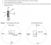
second: I am trying to learn and, trust me, for the past week I've been reading the manual, but it still has a lot of enigmas. one of them is the location of drivers. relative to what? (please, see the attached picture) position on the front baffle? and then I can not find Driver Layout tab. could you be so kind and point me in the right direction?
thank you in advance for any answers and\or suggestions.
I use 2.0.53.2
hello!
first: thank you for your effort in developping such a great software.
second: I am trying to learn and, trust me, for the past week I've been reading the manual, but it still has a lot of enigmas. one of them is the location of drivers. relative to what? (please, see the attached picture) position on the front baffle? and then I can not find Driver Layout tab. could you be so kind and point me in the right direction?
thank you in advance for any answers and\or suggestions.
I use 2.0.53.2
Attachments

"relative to what?"
Relative the listening axis. It usually runs from the listener's ears through the center of the tweeter. Page 3 in https://kimmosaunisto.net/Software/VituixCAD/VituixCAD_Measurement_Preparations_REW.pdf
Relative the listening axis. It usually runs from the listener's ears through the center of the tweeter. Page 3 in https://kimmosaunisto.net/Software/VituixCAD/VituixCAD_Measurement_Preparations_REW.pdf
Usually we specify speaker's main axis more or less formally as invisible Z-axis line from speaker to ear/mic when speaker's main axis (hor=0 ver=0 deg) points towards ear/mic. Starting point of that line is speaker's origin X,Y,Z=0,0,0 mm, and axial location of ear/mic is X,Y,Z=0,0,-listening distance.
Origin does not have to be final because program allows moving of all drivers so that origin moves e.g. from center point of tweeter to center point of mid-range. Whatever meets your design targets.
Driver instances in crossover are located relative to speaker's origin, and possibly rotated and/or tilted relative to direction of main axis.
Hello Kimmo,
A very nice addition to VituixCAD could be to be able to have wavelet analysis from Arta pir files (in the tool section maybe). This would let you visualize the energy of a particular system along the time in a room.
For example, a sub and a sattelite in a room, you will be able to see where you can or cannot put the cut off freq of the sub depending on sub position and room. Also where you will need to do acoustic correction to the room.
- Home
- Design & Build
- Software Tools
- VituixCAD