Crossover S400
How have you gone with your crossover design?
I'm attempting to mimick also - can note some components, but cannot figure out inductor / order
1 x 47 uf 100V Bennic BiPolar B03 Axial Capacitor
1 x Bennic XPP Series 3.3uF 250v Capacitor
1 x Bennic XPP Series 22uF 250v Capacitor
1 x Bennic XPP Series 12uF 250v Capacitor
1 x Bennic XPP Series 15uF 250v Capacitor
1 x 1.8 Ohm 10W Resistor SQP Series
3 x 10 Ohm 10W Resistor SQP Series
4 x ?? Inductors
I will attempt to do so, once I have finished my project to my satisfaction. I was unhappy with my first attempt at a crossover. Following advice here, and making measurements. Actually got to go do that right now......tick tock
How have you gone with your crossover design?
I'm attempting to mimick also - can note some components, but cannot figure out inductor / order
1 x 47 uf 100V Bennic BiPolar B03 Axial Capacitor
1 x Bennic XPP Series 3.3uF 250v Capacitor
1 x Bennic XPP Series 22uF 250v Capacitor
1 x Bennic XPP Series 12uF 250v Capacitor
1 x Bennic XPP Series 15uF 250v Capacitor
1 x 1.8 Ohm 10W Resistor SQP Series
3 x 10 Ohm 10W Resistor SQP Series
4 x ?? Inductors
Yes, that would be great. In the meantime, the delay value in the driver tab seems to do the trick
I already tried restoring original excess delay at given frequency, but it did not work well enough without removing also remaining phase difference. So that feature is not yet added.
Delay in Drivers tab just don't work with full off-axis measurement set 0-180 deg because excess delay depends on off-axis angle. Minimum phase extraction removes excess delay from all measurements causing significant error to high off-axis angles with boxed speakers, horns, deep wave guides, large (PA) coaxials etc.
Another error with MP extraction is missing support of polarity inversion so dipoles and leaking gradient radiators are not supported. Polarity could swap randomly within measured frequency range to high off-axis angles so inversion status is impossible set by angle. Especially dipoles with electro-dynamic should be designed including rear sector so MP extraction does not have any changes.
As mentioned (maybe too many times) already in this thread, MP extraction or any other timing normalization such as single channel measurements with USB mics shouldn't be used other than near field or in-room response or for designing to single spot on-axis where timing differences in phase response are not needed or some constant delay (or Z offset) is possible to use to delay single response to design axis. Take it or leave it 🙂
I've been quite strict with this MP topic so few comforting words for Umik-1 and OmniMic v2 owners who don't have any plans or possibilities to purchase gear which is able to measure sound flight time in dual channel mode i.e. with internal or external electrical reference.
Error due to minimum phase extraction depends on acoustical/mechanical construction. Error could be really small and insignificant in practice if sound path length from center point of each driver to 180 degrees off-axis is close to equal. Excess delay of typical flat cones, domes and planars is quite constant (0 s) to whole front sector within 0...80 deg when microphone "sees" the dust cap. Delay differences between drivers stay quite constant also to rear sector if distance from center point of each driver to baffle edge is equal for all drivers i.e. drivers are installed to common baffle with constant width (valid in horizontal plane).
Normal unidirectional cone drivers need small delay[us] to Drivers tab for acoustic center offset. Deeper unidirectional drivers such as PA coaxials need longer e.g. 420 us ~ 140 mm, but that also works pretty well to rear sector because cone and HF driver have the same center point (X,Y) and path length from center to 180 degrees.
Also dipole speakers can be simulated with MP data if all drivers are flattish dipoles and distance from center to rear stays constant.
If dipole speaker has unidirectional tweeter, radiator should be quite large or directive instead of small omni. Otherwise sum of inverted middle and not inverted omni high goes wrong to rear sector at XO range because MP extraction has corrupted polarity of dipole part while mono tweeter is okay.
Polarity to back will be wrong, but that is not optimized with crossover so who cares 🙂
Vertical plane will have more errors because path length to rear varies and is longer and more complex. This affects also to dual channel measurements if vertical plane is mirrored from horizontal instead of actual measurements. Errors due to MP extraction are just different.
BUT significant errors to rear sector are expected if baffle size if each unidirectional driver is much different. For example B&W 801 style. Differences in the shortest path length from center point to rear could be close to 200 mm so MP extracted data and reality are not equal for sure. Simulator sums responses to back with totally wrong timing differences.
All this needs quite much explanation, thinking, guessing and decisions which are not necessarily correct. One simple standard suitable for any construction is nice target, but not necessarily the easiest for all individuals. Possible and reality for many of us, but not all.
Member
Joined 2003
Thank you for a detailed response. I apologize, I didn't read back through 200+ pages of discussion for references to min phase and HBT.
I want to be clear, I am not wanting to generate min phase response, and I am not using a single channel USB mic, but a proper 2 channel measurement that includes excess phase from the FFT window start point. My intent would be only to increase accuracy on the measured phase by filling in the data beyond 20kHz and below the noise floor. I understand, with the specific delay may change based on off-axis angle, that the process can become quite tedious to apply a specific delay to each angle manually.
As you suggest, the measured phase without HBT correction should be "good enough", so I will measure loudly and take an average of several measurements to ensure the noise floor is as low as possible. I have capability to measure at 96kHz, so I can gather data to about 48kHz however my mic calibration ends at 20kHz so I have to make some assumptions of the calibration curve beyond 20kHz.
I will follow the process as you've outlined. I am quite happy with my results thus far with VituixCAD, the inclusion of power response, DI, and the optimizer put it a step above all other freely available simulation software available. Thank you!
^Don't you measure near field or use sweep or why noise floor is a problem? I measure also near field with single slow sweep (without averaging). There is some noise at LF, but that doesn't affect to design. FIR filter generated with automatic TF calculation would have unnecessary corrections for very low frequencies, but level is low (~35 dB below) and will be removed from IR due to limited taps and window function anyway.
One quick and dirty action would be deleting rows <20 Hz from frd files. Program extrapolates down to 5 Hz, though that won't be minimum phase either. Extrapolation as MP would be smarter, but it's complex and slow action requiring polarity detection too. I've been thinking that many times, but existing fast non-MP implementation has been quite okay.
One quick and dirty action would be deleting rows <20 Hz from frd files. Program extrapolates down to 5 Hz, though that won't be minimum phase either. Extrapolation as MP would be smarter, but it's complex and slow action requiring polarity detection too. I've been thinking that many times, but existing fast non-MP implementation has been quite okay.
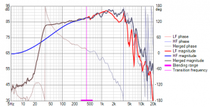
One example measured with CLIO fw-02 & 12 QC. Noise is limiting to about 40 dB below merged SPL when cone is measured near with 0.283V (-20 dB) and passive radiators with 0.9V (-10 dB).
Attachments
Last edited:
2.0.55.0 (2020-09-10)
Enclosure
* List of most recent enclosure projects as dropdown menu replaced with table of enclosure projects.
2.0.54.0 (2020-09-08)
Main
* Open, Short, Invert and Mute commands moved from context menu to O, S, I and M buttons below crossover schematic.
Calculator
* Added 'Maintain delay' checkbox and text box to Response tails group of Minimum phase function. Excess group delay can be added to maintain phase shift of original response at given frequency. Note! Delay calculation cannot handle inverted polarity because MP response is uninverted by nature.
Member
Joined 2003
Sorry about revision spam.
2.0.55.1 (2020-09-10)
Enclosure
* Added (+) 'Save all traces as overlays' and (-) 'Clear all overlays' buttons.
* Added 'Overlay name suffix' text box.
2.0.55.1 (2020-09-10)
Enclosure
* Added (+) 'Save all traces as overlays' and (-) 'Clear all overlays' buttons.
* Added 'Overlay name suffix' text box.
2.0.55.2 (2020-09-11)
Main
* Added (+) 'Save all traces as overlays' and (-) 'Clear all overlays' buttons.
* Added 'Overlay name suffix' text box.
* Reference angle text box moved above graphs.
* SPL max checkbox and text box moved above graphs.
* SPL span expand/compress buttons moved above graphs.
Enclosure
* Overlay buttons and text box moved up.
* Trace color labels removed because colors are not fixed anymore.
* Ovl (+) does not clear existing overlays.
do not know if this have been adressed but when i am using the enclosure feature and click the radio button for a qtc value in the align tab i get very strange reading, i must double click the radio button to get correct reading
example: if i click for a qtc of say 0.9 and then click for a qtc of 0.5 then every graph is updated wrongly, i need to click the radio button once more for qtc 0.5 to get correct readings, is it supposed to work like that?
example: if i click for a qtc of say 0.9 and then click for a qtc of 0.5 then every graph is updated wrongly, i need to click the radio button once more for qtc 0.5 to get correct readings, is it supposed to work like that?
^9/11 bug. Setting of Vb jumped two rows up yesterday causing "phase shift". New setup with the same rev number is fixed.
Hi kimmosto,
Is there any way to download VituixCAD 1.1.33? I have some workflow that still works better in VituxCAD 1, but I'll move to VituixCAD 2 soon. Thank you
Is there any way to download VituixCAD 1.1.33? I have some workflow that still works better in VituxCAD 1, but I'll move to VituixCAD 2 soon. Thank you
Rev 2.0.56.0 (2020-09-17)
* Y-axis max can be adjusted with mouse wheel, and span (dB only) with Ctrl + mouse wheel when mouse cursor is closer to Y-axis to be adjusted (Y left, Y2 right).
Exceptions: Directivity chart follows max and span settings of SPL chart. Directivity index has common span with SPL. DI maximum = span - major grid interval. Phase angle has constant Y2-scale +180…-180 deg.
* Overlays can be scaled with Shift + mouse wheel or Ctrl + Shift + mouse wheel.
Options
* Magnitude axis max and span settings changed from combo boxes to text boxes.
Exceptions: SPL/Directivity span and Filter gain span still as combo box.
* Magnitude axis settings are initial values.
Enclosure
* Automatic Y scaling removed from Power and Force charts.
Member
Joined 2003
Sorry if this has been asked previously, but I had an idea for quick crossover simulation.
With VituixCAD there is the ability to design passive crossovers as well as design DSP filters using biquads that can be directly loaded into a miniDSP. Could a method be developed, to design an passive crossover, and have its transfer function converted to DSP biquads, this way I could load in a DSP filter that accurately represents the passive filter without having to build the filter? The idea is so that a passive crossover can be evaluated without building, and some tweaking could be completed before a parts order is placed.
Thanks!
Last edited:
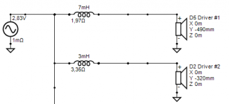
Kimmosto, i found that the crossover does not correctly calculate the inductor resistance. Smaller inductance should have less resistance. The wire diameter is the same.
Attachments
Last edited:
Kimmosto, i found that the crossover does not correctly calculate the inductor resistance. Smaller inductance should have less resistance. The wire diameter is the same.
DCR cannot be calculated by L and gauge alone so it's obvious that whole purpose of the feature is not to give exact result. It just tries to guess change to previous value when you change either L or gauge with up/down key or mouse wheel. Guessing is based on simple statistics from typical/available air core inductors between 0.5 and 2.0 mm.
Personally I think that feature sucks, but negative feedback is not much received. I guess most of the users realize that final DCR should be verified from datasheets of coil manufacturer.
Could a method be developed, to design an passive crossover, and have its transfer function converted to DSP biquads
Sorry but this is not coming as automatic. User can design active filter with generic active blocks, but blocks should be selected and initial parameter values entered manually. Responses at driver terminals can be optimized (with Optimizer) with transfer functions of passive filter. Then you can export biquad coefficients including both XO and EQ to miniDSP app with IIR only.
FIR gear is needed to speed up process significantly. VituixCAD is able to export transfer function at driver terminals as impulse response. Impulse responses are imported to Equalizer APO or miniDSP with FIR or compatible. That takes few minutes. This was discussed months ago.
- Home
- Design & Build
- Software Tools
- VituixCAD