Usually we specify speaker's main axis more or less formally as invisible Z-axis line from speaker to ear/mic when speaker's main axis (hor=0 ver=0 deg) points towards ear/mic. Starting point of that line is speaker's origin X,Y,Z=0,0,0 mm, and axial location of ear/mic is X,Y,Z=0,0,-listening distance.
Origin does not have to be final because program allows moving of all drivers so that origin moves e.g. from center point of tweeter to center point of mid-range. Whatever meets your design targets.
Driver instances in crossover are located relative to speaker's origin, and possibly rotated and/or tilted relative to direction of main axis.
Thank you for clarifying this for me
2.0.53.4 (2020-09-04)
Enclosure
* Input signal is possible to enter as power to Re+Rg in addition to voltage. Power option is selected with P checkbox, and voltage with U checkbox. Default value (2.83 V or 1.0 W) is set by double-clicking unit label (V or W).
2.0.53.3 (2020-08-30)
Enclosure
* Local driver database is saved automatically when driver is added or modified.
* Program asks 'Save changes to local driver database?' if data is changed and Enclosure tool is still open and user is closing VituixCAD.
* Added more decimals to Cms, Vas and Mms to support very small drivers.
* Enabled calculation of missing Vas by Cms to Add/Edit driver window.
* Added T (tweeter) to driver Type listbox in Add/Edit driver window.
* Added SPL max checkbox and text box for manual SPL max adjustment. Setting is saved to user.config, but not to enclosure project.
* SPL span expand and compress buttons moved up. Added more span options and current span to tooltip.
Main
* Context menu of crossover schematic shows indeterminate status of Open, Short, Invert, Mute and Rotate commands i.e. some but not all are checked.
2.0.53.2 (2020-08-18)
Main
* Added Mute checkbox to Drivers tab.
Enclosure
* Input signal is possible to enter as power to Re+Rg in addition to voltage. Power option is selected with P checkbox, and voltage with U checkbox. Default value (2.83 V or 1.0 W) is set by double-clicking unit label (V or W).
2.0.53.3 (2020-08-30)
Enclosure
* Local driver database is saved automatically when driver is added or modified.
* Program asks 'Save changes to local driver database?' if data is changed and Enclosure tool is still open and user is closing VituixCAD.
* Added more decimals to Cms, Vas and Mms to support very small drivers.
* Enabled calculation of missing Vas by Cms to Add/Edit driver window.
* Added T (tweeter) to driver Type listbox in Add/Edit driver window.
* Added SPL max checkbox and text box for manual SPL max adjustment. Setting is saved to user.config, but not to enclosure project.
* SPL span expand and compress buttons moved up. Added more span options and current span to tooltip.
Main
* Context menu of crossover schematic shows indeterminate status of Open, Short, Invert, Mute and Rotate commands i.e. some but not all are checked.
2.0.53.2 (2020-08-18)
Main
* Added Mute checkbox to Drivers tab.
The "normal" way things are shown on the forums in NA is you set the mic on the tweeter axis ~50cm and never move the microphone or the speaker. All drivers are measured with the microphone and multiway speaker in the same location.
http://audio.claub.net/software/FRD...curate In-Room Frequency Response to 10Hz.pdf
This would be how many people make measurement to use Jeff Bagbys Passive Crossover Designer 8 (or Xsim). Obviously this does not account for any off axis responses and why I am looking to include off axis measurements.
I just finished up my Arta Turntable and I am trying to understand the instructions in,
https://kimmosaunisto.net/Software/VituixCAD/VituixCAD Measurement Preparations.pdf
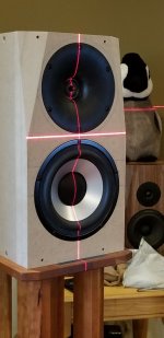
I have included a few pictures to see if I am understanding the instructions correctly
Starting positions for measurements, not necessarily in this order,
Measure woofer 0º -180º in X axis, microphone centred on woofer and on axis, using real world X rotation,
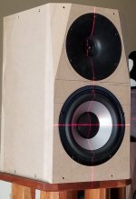
Measure tweeter 0º -180º in X axis, microphone centered on tweeter and on axis, using real world X rotation,
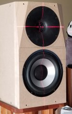
Measure woofer -180º 0º -180º in Y axis, microphone centered on woofer and on axis, using real world X rotation by placing speaker on its side,
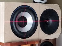
Measure tweeter -180º 0º -180º in Y axis, microphone centered on tweeter and on axis, using real world X rotation by placing speaker on its side,
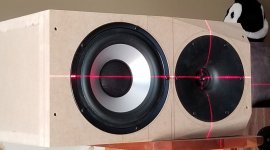
(pay no attention the stand poking out from under the speaker, I know that would be a diffraction problem if measurements were done this way, pretend the speaker overhangs the stand... 🙂 )
Is this how the measurements are to be done?
How do you account for possible differences in microphone x/y/z locations as the speaker and microphone are repositioned for the four different measurement positions?
Thank you,
David.
http://audio.claub.net/software/FRD...curate In-Room Frequency Response to 10Hz.pdf
This would be how many people make measurement to use Jeff Bagbys Passive Crossover Designer 8 (or Xsim). Obviously this does not account for any off axis responses and why I am looking to include off axis measurements.
I just finished up my Arta Turntable and I am trying to understand the instructions in,
https://kimmosaunisto.net/Software/VituixCAD/VituixCAD Measurement Preparations.pdf
I have included a few pictures to see if I am understanding the instructions correctly
Starting positions for measurements, not necessarily in this order,
Measure woofer 0º -180º in X axis, microphone centred on woofer and on axis, using real world X rotation,

Measure tweeter 0º -180º in X axis, microphone centered on tweeter and on axis, using real world X rotation,

Measure woofer -180º 0º -180º in Y axis, microphone centered on woofer and on axis, using real world X rotation by placing speaker on its side,

Measure tweeter -180º 0º -180º in Y axis, microphone centered on tweeter and on axis, using real world X rotation by placing speaker on its side,

(pay no attention the stand poking out from under the speaker, I know that would be a diffraction problem if measurements were done this way, pretend the speaker overhangs the stand... 🙂 )
Is this how the measurements are to be done?
How do you account for possible differences in microphone x/y/z locations as the speaker and microphone are repositioned for the four different measurement positions?
Thank you,
David.
Last edited:
The measurement process as presented is correct.
The front baffle is assumed to be perpendicular to the mic, which in this case looking at the speaker, it is.
Attention must be paid that the mic distance to the baffle surface when measuring each DUT is maintained as constant as possible, reasonable within few mm.
Using ARTA semi-dual (or full dual) measurement process will assure all signals are locked to the same impulse start.
Measured this way each driver has initial values for X,Y,Z zero.
Then, if designing for a tweeter-axis, the tweeter will remain at X,Y.Z zero (even if the tweeter is set back in a WG like in your case), and the midbass will be at X,Z zero and Y= -160/165 mm aprx, assuming the WG148 diameter of 148 mm and cca 170 mm for the midbass, plus some 15 mm inbetween.
Hope this is what you were asking. It is well documented in V2 Measurement preparation document.
^^Basically yes, but I don't measure vertical plane with circular drivers - especially in small speaker where distance from center point of woofer to bottom and side walls is quite equal. Error in power response will be less than 0.5 dB at baffle step hump (@mid-range) without separately measured vertical data. Effect of vertical lobing is several times bigger with multi-way. Simulator handles that with response mirroring (from hor to ver) and virtual XYZ-locations of measurement data i.e. center point of drivers.
Situation will be totally different with ribbons/planars and other hor/ver asymmeyrical radiators such as elliptical and bi-radial horns. These should be measured in both planes if possible. Heavy tower speakers are difficult without modular construction.
Your box is so small that you could also consider measuring both drivers in horizontal plane only at middle elevation between woofer and tweeter (without moving mic vertically). Angle error at 1 m will be about 4 degrees which is quite acceptable for a ring radiator in wave guide. You miss exact axial response which is not valuable design axis for that type of radiator.
Maintaining rotation center in the center point of each DUT is sometimes quite difficult due to swinging of stand etc. Significance of error depends on XO frequency. Variation within 2 mm is usually possible and okay with XO frequencies below 4 kHz. I usually check distance from mic to center of DUT to three directions: -90, 0 and +90 deg. Phase interpolation in the simulation collapses anyway to angles >>90 deg, but front sector should be in control.
So, for a small two way like this, separately measuring the the woofer and tweeter in X rotation 0º-180º at one meter out with the microphone in a single position is adequate?
How would "Y" be entered in VituixCAD for driver position in a measurement taken this way? Use real numbers +- from mic/baffle position, or zero?
This box was really to test a number of tweeters on waveguides with this woofer.
You specifically mentioned ring radiators in a waveguide as not necessarily requiring a "face on" measurement, would that apply to domes in a WG as well?
(I plan to use full dual measurements)
Thank you,
David.
Both Y's zero....
May I please ask about the XT25 ring tweeter attachment to the WG148?
Did you remove the front plate and fabricated an adapter, or it fits over the front plate as-is? Is there a gap to be filled?
Sorry for OT.
May I please ask about the XT25 ring tweeter attachment to the WG148?
Did you remove the front plate and fabricated an adapter, or it fits over the front plate as-is? Is there a gap to be filled?
Sorry for OT.
Draki,
The 3D printed adapter is one of my own design, not quite ready for prime time yet, still working on it.
With full dual measurements preserving phase, does tweeter Z offset still need to be determined and entered in driver settings?
Thank you,
David.
The 3D printed adapter is one of my own design, not quite ready for prime time yet, still working on it.
With full dual measurements preserving phase, does tweeter Z offset still need to be determined and entered in driver settings?
Thank you,
David.
So, for a small two way like this, separately measuring the the woofer and tweeter in X rotation 0º-180º at one meter out with the microphone in a single position is adequate?
Probably yes. But now you have motorized table for making also diy science and compare results of full and simplified measurement sequences with small 2-way speaker. I have done comparison with diffraction simulations loaded to main program as measurement data. Power, DI and many other CTA-2034 reports contain so many off-axis responses that some approximation happens anyway.
How would "Y" be entered in VituixCAD for driver position in a measurement taken this way? Use real numbers +- from mic/baffle position, or zero?
Here we are just cheating the simulator (and ourselves) that measurement data was captured by official recommendation; with individual rotation center for both drivers at axial Y. So you can locate center point of each driver instance as you like: tweeter=0, woofer=-160 or tweeter=60, woofer=-100, ....
You specifically mentioned ring radiators in a waveguide as not necessarily requiring a "face on" measurement, would that apply to domes in a WG as well?
Same story with any driver giving quite close to same response to 0 deg and 4 deg. Long ribbons, ATMs and other planars need actual 0 deg ver measurement due to "excessive" vertical directivity. Vertical -4 deg off-axis would be radically something else than on-axis.
Effects of small measurement cheating reduce if you can measure at 1.5 m or 2 m. My instructions are written for poor diy audio labs such as our 25m2 living room (ceiling at 247 cm) requiring short time windows.
With full dual measurements preserving phase, does tweeter Z offset still need to be determined and entered in driver settings?
Maybe I confuse more but we are not locating actual or simulated drivers or acoustic centers to crossover simulator. X,Y,Z location of driver instance in crossover simulation is rotation center of measurement data loaded to driver model (in Drivers tab). Measurement data is also possible to tilt (vertically) and rotate (horizontally) around it's center point which simulates locating driver e.g. to side, top or back panel of the speaker.
So Z=0 mm for all drivers instances if rotation center has been at the same distance from microphone while off-axis measurement sequences. All timing differences between rotation center and assumed acoustical center of drivers are stored in measurement data assuming that all frequency responses are measured and exported by instructions: dual channel connection & mode and common Reference time.
Both Y's zero....
This is correct if also vertical plane is measured at common Y and loaded to simulation.
But if both drivers are measured at common Y in horizontal plane only, driver instances in XO must have different Y mm. Otherwise result is wrong due to ignored vertical lobing.
if also vertical plane is measured at common Y and loaded to simulation.
Quick but important reminder that measuring also vertical plane at common mic Y (in the middle of drivers) is NOT recommended. 1/48 points per octave frequency scale cannot handle phase responses if distance between DUT and microphone i.e. timing varies too much. Excessive variation causes phase wrapping errors at HF in addition to IR shifting within time window at fixed position (=dual channel).
Common mic Y position for both drivers of a small 2-way is valid method if only horizontal plane is measured, and vertical plane is mirrored from horizontal data by the simulator.
So all good simply by following instructions.
Member
Joined 2003
Hello,
I have started using VituixCAD and have found it to be very good. Quite accurate simulation vs my measurements.
On the merger tool, I would like to see some Hilbert-Bode transform available to help increase phase accuracy. Some ability to overlap the HBT with the original measurement will be necessary to adjust delay to retain measured "time of flight".
On the merger tool, I would like to see some Hilbert-Bode transform available to help increase phase accuracy.
Merger tool has minimum phase extraction already. Should be used 'with GD of HF' checked to maintain timing differences between different drivers and different off-axis directions.
Minimum phase calculation could actually reduce phase accuracy of far field measurements processed with time window function. Typically time window function causes more error to magnitude response than phase response. Basically we would get more accurate magnitude response by calculating it by phase response. This is one reason why minimum phase extraction is generally not recommended without manual manipulation of high pass slope of driver; cropping at the lowest reliable frequency and adding assumed high-pass slope e.g. 12 dB/oct manually. This can be done with Calculator tool for all measured off-axis angles at once, but after that advantages of 'with GD of HF' function are lost so don't do it before merging.
Last edited:
Member
Joined 2003
Hi kimmosto,
Minimum phase extraction and Hilbert Bode Transform are not the same, at least not strictly what I was suggesting. What I am speaking of is a tool to provide "tails" to extend the low and high frequency slope of a measured response. This is to remove the noise floor from the measurement as well as provide a slope of the response beyond the measured frequency range. Doing so increases the phase accuracy in the pass band, and of course minimum phase result will be achieved, so delay must be added back in to retain the time of flight. Since the "tails" affect the phase in the high and low ends of the frequency range, the delay added should match the measured phase in the middle of the measured passband. It works very well, and has been standard process in SoundEasy for years. The intent is not simply to generate a minimum phase result, but to simply correct the phase in the frequency extents due to noise floor and measured frequency range limitations.
Minimum phase extraction and Hilbert Bode Transform are not the same, at least not strictly what I was suggesting. What I am speaking of is a tool to provide "tails" to extend the low and high frequency slope of a measured response. This is to remove the noise floor from the measurement as well as provide a slope of the response beyond the measured frequency range. Doing so increases the phase accuracy in the pass band, and of course minimum phase result will be achieved, so delay must be added back in to retain the time of flight. Since the "tails" affect the phase in the high and low ends of the frequency range, the delay added should match the measured phase in the middle of the measured passband. It works very well, and has been standard process in SoundEasy for years. The intent is not simply to generate a minimum phase result, but to simply correct the phase in the frequency extents due to noise floor and measured frequency range limitations.
Member
Joined 2003
I'll play around a bit more and see if I can reproduce what I am looking for with the calculator tool. Thanks!
Can't move optimizer target line
Hi forum--
I'm trying to change the optimizer target line. I watched a video. And the manual just says "Target lines are set in SPL and Power & DI charts". But when I click and drag on the ends, they don't move. I have the optimizer window up. In the video, the target are click-n-dragged around. But I can't get it to grab.
What am I doing wrong?
Thanks!
--Myles
I'll play around a bit more and see if I can reproduce what I am looking for with the calculator tool. Thanks!
Some day I might add saving of group delay to Minimum phase function in Calculator. That would enable manipulation of time locked dual channel measurements with minimum phase extraction. Normally MP function in Calculator or anywhere else does not play any role when following my measurement and design instructions. For example I never use it.
Last edited:
Member
Joined 2003
Some day I might add saving of group delay to Minimum phase function in Calculator. That would enable manipulation of time locked dual channel measurements with minimum phase extraction. Normally MP function in Calculator or anywhere else does not play any role when following my measurement and design instructions. For example I never use it.
Yes, that would be great. In the meantime, the delay value in the driver tab seems to do the trick, but I haven't found a straight forward method in Vituix to determine the delay needed to restore the measured phase from a minimum phase result using the calculator.
- Home
- Design & Build
- Software Tools
- VituixCAD