What's the correct way of going about this now?
Positive mic offset Y is negative driver offset Y. But if you're simulating also in-room response with floor/ceiling reflections, you need to adjust floor/ceiling Y to the same direction with driver offset Y to maintain constant distance between drivers and reflecting surface i.e. emulating just mic movement.
P.S. Response interpolation in vertical plane close to 0 deg does not work properly at the moment. This causes some error with H.F. ribbons and planars which are measured in vertical plane too. Mirroring from horizontal to vertical is okay so domes etc. measured in horizontal only work okay. I'll try to fix that in few days.
Rev. 2.0.53.0 (2020-07-31)
Main
* Fixed response interpolation within axial and the smallest measured vertical off-axis angle.
Merger
* Added 'Count' column to Low frequency part response list. Enables dB scaling by count of radiators in case number of vents is not equal to number of cones and single near field measurement is loaded for multiple radiators. Note that all passive radiators in the same box must be measured separately to get correct sum.
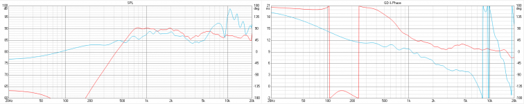
Referring to my post 2256 VituixCAD I'm attaching picture with drivers characteristics.
Maybe phase wrap (cone breakup?) is source of simulation mismatch above 7kHz? But still -12us (-4mm) is mysterious for me. If mic distance from baffle is 100cm then I can read from impulse responses:
Tweeter - 99.93cm
Woofer - 102.08cm
Woofer measured on tweeter axis - 102.44cm
Maybe phase wrap (cone breakup?) is source of simulation mismatch above 7kHz? But still -12us (-4mm) is mysterious for me. If mic distance from baffle is 100cm then I can read from impulse responses:
Tweeter - 99.93cm
Woofer - 102.08cm
Woofer measured on tweeter axis - 102.44cm
Attachments
Is my setup ok? Am I doing everything correctly?
Your text looks okay.
As you can see the simulation result isn't ideal.
I don't see any simulations with XO yet. Just plots of measurements. Let's evaluate ideality once you have simulated complete speaker.
I wonder about Delay option for woofer. Should I modify it if I've made dual channel measurements?
No, or Delay[us] value in Drivers tab should be exactly the same for woofer, mid and tweeter.
Whole idea of dual channel measurement is to include also delay difference (on axis) between drivers (by rotation center on baffle surface). Purpose of crossover/filter is to shape measured magnitude and phase responses of drivers to get targets in project cabinet.
During exporting every frequency response in Arta I've set start point on 300th sample, predelay based on tweeter measurement and end marker I've set the same on every measurement but not to take any reflections.
The latest instructions recommend using Convert IR to FR of VituixCAD for this but polar export of ARTA works too of course though it's not so visual.
Hello,
Your software is great but I'm missing the price of the components.
Is it possible to replace the column "expression" by "cost" and make it appear in "parts list"?
Thank you very much for your help.
Your software is great but I'm missing the price of the components.
Is it possible to replace the column "expression" by "cost" and make it appear in "parts list"?
Thank you very much for your help.
^My philosophy has been that seller says the price. Parts list can be copied to spreadsheet or e-mail with added price column if designer/buyer wants to remind seller about MSRP or quotation. Price has nothing to do with technical design.
^^About Expression field, it's for formula or variable of library blocks with calculated component/parameter values. Can't be replaced with anything.
Hi Kimmo,
today I got confused a bit:
Its about setting the delay on the driver-page:

Shouldn't a increase of delay result in a decrease of the z-Position?

thanks and regards
Matthias
today I got confused a bit:
Its about setting the delay on the driver-page:
Shouldn't a increase of delay result in a decrease of the z-Position?
thanks and regards
Matthias
^Coordinate system is compatible with LspCAD i.e. delay in sound increases when distance from radiator to virtual mic/ear increases. This is the most logical system imo though sign of Z is opposite compared to some coordinate systems used in mathematics.
See user manual and measurement instructions for more information.
See user manual and measurement instructions for more information.
^User manual, page 8 in pdf version for driver instances: "Z[mm] is horizontal distance coordinate; negative closer to mic and positive further from mic". Timing adjustment for frequency response data in Drivers tab has the same logic.
There is also image with X,Y,Z axis arrows in Measurement with ARTA and REW. In the beginning of page 3. Some text too so this should be 100% clear.
There is also image with X,Y,Z axis arrows in Measurement with ARTA and REW. In the beginning of page 3. Some text too so this should be 100% clear.
Last edited:
One more important thing. Delay [us] parameter in Drivers tab is NOT driver's location. It's just timing/phase adjustment of frequency response data if frequency responses are not measured and converted from IR to FR according measurement instructions (linked in my signature). Normally Delay [us] is 0 us for all drivers in Drivers tab.
Driver's location relative to speakers origin, rotation and tilt is set to X,Y,Z,R,T parameters of driver instance in crossover schematic. All this assuming that measurements are done according instructions (rotation center at the center of each driver, driver's axis is 0.0 deg also in vertical plane, dual channel mode, common reference time for all drivers etc).
Driver's location relative to speakers origin, rotation and tilt is set to X,Y,Z,R,T parameters of driver instance in crossover schematic. All this assuming that measurements are done according instructions (rotation center at the center of each driver, driver's axis is 0.0 deg also in vertical plane, dual channel mode, common reference time for all drivers etc).
Last edited:
kimmosto,
if to measure each driver not as in the instructions, but from one point, which is located on the tweeter axis at the listening position, then such frequency response + phase response will take into account all the distances between the drivers, as well as the distance from the listening point to each driver. In this case, the driver Y coordinate for each driver should be = 0?
if to measure each driver not as in the instructions, but from one point, which is located on the tweeter axis at the listening position, then such frequency response + phase response will take into account all the distances between the drivers, as well as the distance from the listening point to each driver. In this case, the driver Y coordinate for each driver should be = 0?
Hi Kimmo,
thank you. its clear to me now.
But technically it does not make a difference, if i set up a delay (eg equals -10mm) or set up an z-Position of the the speaker of -10 mm? or does it make a difference in the calculation?
thank you. its clear to me now.
But technically it does not make a difference, if i set up a delay (eg equals -10mm) or set up an z-Position of the the speaker of -10 mm? or does it make a difference in the calculation?
kimmosto,
if to measure each driver not as in the instructions, but from one point, which is located on the tweeter axis at the listening position, then such frequency response + phase response will take into account all the distances between the drivers, as well as the distance from the listening point to each driver. In this case, the driver Y coordinate for each driver should be = 0?
Correct. X,Y,Z,R,T of all driver instances in XO should be 0,0,0,0,0 if all drivers are measured so that rotation center while off-axis sequences is fixed e.g. center of tweeter.
BUT 🙂 That measurement method requires long time window i.e. huge space or anechoic and measuring at nominal listening distance (2-2.5 m) to support measurement of whole vertical plane of big constructions such as 2 meters high multi-way towers. Otherwise vertical off-axis responses, power, DI and ER results could be quite much wrong.
This is the reason why I have constant bad attitude towards single center point method, though it's okay for really tiny 2-ways also in vertical plane. In case designer measures just axial responses at single spot, it's also recommended to use XSim basic or compatible which does not contain any acoustical simulation. Just XO simulation multiplied by single frequency response file - whatever it is. I guess that would not end repeating the same question and answer here. This is about tenth time...
Last edited:
But technically it does not make a difference, if i set up a delay (eg equals -10mm) or set up an z-Position of the the speaker of -10 mm? or does it make a difference in the calculation?
It's different, though 10 mm is not much if XO point is not very high:
Delay is constant to all off-axis angles, but Z +10 mm movement of driver instance is 20 mm shorter to 180 deg than 0 deg because geometry is calculated as direct distance (X-rays). Direct distance from center point (=rotation center) of driver to virtual mic affects to measured magnitude and phase loaded in Drivers tab. So delay and Z mm are compatible to 0 degrees only, but other off-axis angles exist too if drivers are measured by instructions 🙂
Last edited:
Correct. X,Y,Z,R,T of all driver instances in XO should be 0,0,0,0,0 if all drivers are measured so that rotation center while off-axis sequences is fixed e.g. center of tweeter.
BUT 🙂 That measurement method requires long time window i.e. huge space or anechoic and measuring at nominal listening distance (2-2.5 m) to support measurement of whole vertical plane of big constructions such as 2 meters high multi-way towers. Otherwise vertical off-axis responses, power, DI and ER results could be quite much wrong.
This is the reason why I have constant bad attitude towards single center point method, though it's okay for really tiny 2-ways also in vertical plane. In case designer measures just axial responses at single spot, it's also recommended to use XSim basic or compatible which does not contain any acoustical simulation. Just XO simulation multiplied by single frequency response file - whatever it is. I guess that would not end repeating the same question and answer here. This is about tenth time...
I do understand your (valid) concerns. But in the case of a ground-plane measurement (GPM) of small cabinets it will be difficult to adjust the tilt angle for each driver y-position. Especially if the drivers are positioned close to each other.
In this case I would stick with one common MIC position? Do we agree?
^Ground plane measurement is different case, but I'm too busy at the moment to specify officially & finally how it should be done for VituixCAD. Maybe after few days.
Ground plane affects to diffraction so it not good for direct HF and small mid radiators. But it's very good and recommended for special LF radiators such as leaking cardioid which cannot be simulated simply with enclosure and diffraction simulators i.e. baffle loss and full space directivity simulations are not available at least with VituixCAD.
Small tilting of speaker for ground plane measurement of single woofer or pair should not be a problem to ensure that exact axial response is captured e.g. for cone break-up filtering. Rotation center should stay in the center of driver of course, and distance equal to far field measurements of mids and tweeter - or exactly known to enable magnitude and delay scaling.
To me it looks that ground plane does not change much. Just mic position and speaker tilt while measuring woofer(s). But we can return to this topic later.
Last edited:
I though this thread might be of interest. It documents someone's experience with doing ground plane measurements:
Measuring Response: How close is "close enough" to anechoic?
Measuring Response: How close is "close enough" to anechoic?
- Home
- Design & Build
- Software Tools
- VituixCAD