You were right if I was about some personal preference like different value, brand of any component but we are talking about some fundamental design considerations here. What about taking a look at corresponding DS section below?
I took a look. I still choose not to follow those recommendations in this particular instance.
For example on 1. I choose not to use an RC filter for supply purity, rather I use an LC filter (a ferrite bead provides the L). I consider LC to give superior performance here - it negates the need for so many supply decouplers. Of course if a series R is used for filtering the need for decoupling becomes much more critical.
On 2 I am not using a ground plane nor am I splitting return current paths.
On 3 I use two decoupling caps for 6 chips. This is based on experience with my multiple paralleled DAC (GrossDAC) where I used a total of 12 ceramics for 36 chips. That board though did have a groundfill. I choose not to shield the digital input lines with ground traces.
Even if your "design choice in respect of decoupling" in contradiction with Philips engineers whom also stating voltage compliance values on same datasheet?
You have lost me - I am not seeing any voltage compliance spec apart from at DC for the TDA1387. The TDA1543 has an AC voltage compliance spec and I'll just mention in passing every one of the passive I/V implementations I've seen violate it.
Yes you are free of choosing different value of voltage compliance too
Why is this relevant? I'm 'respecting' the DC voltage compliance spec in this design. If I violate that the DAC won't put out the stated current so it makes a large difference to the operation of the DAC. Unlike the case of changing the supply decoupling details.
but I'm also free to bring "your own design of choice" on table without building, testing and measuring since DS says something different.
The application information isn't the same as the limits in the DS table so I'm not sure of your point.
Subjective? I thought you were aware of that I was suggesting you to just respecting the DS.
You mentioned 'a bit disappointed' that's what I was referring to. Why mention that if you didn't want a comment on it?
It is metastabile only in the way when 1 x flip flop is used per digital line.
And that wrong way is most common.
Yes, its the way used on the Audiophonics board.
But when designed as in school literature, with 2 cascaded, serial flip-flops, it is not metastabile. And all lines should be "reckloked".
I agree that's the textbook way to resync an async signal. But it does require knowledge of the metastability resolution time of the flip flop, not a parameter that is given in the DS.
I made an omission when talking about asynchronous reclocking - the metastability isn't the most serious issue. I forgot to point out that the peak to peak jitter when an audio clock is resynchronized with an asynchronous 50MHz clock becomes 20nS. Not at all an amount to be proud of when typical S/PDIF receivers achieve of the order of 0.1nS.
You mentioned 'a bit disappointed' that's what I was referring to. Why mention that if you didn't want a comment on it?
Maybe because you are avoiding something critical in digital circuit design without some sensible reason? Isn't this a valid reason for disappointment? Sorry but I can't follow you...
Last edited:
Maybe because you are avoiding something critical in digital circuit design without some sensible reason?
You didn't follow my explanation then?
Isn't this a valid reason for disappointment? Sorry but I can't follow you...
Disappointment is the result of having unreasonable expectation. See : Dealing With Disappointment | Psychology Today
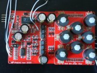
Prototype 9th order filter
My wife managed to find a way to squeeze 8 inductors onto a board outline designed for 6 🙂 The stop band rejection for this filter is in theory better than 100dB but in reality this number is going to depend on circuit parasitics which I'm not able to quantify accurately. Listening will reveal whether there's any benefit of this compared to the 7th order filter. If anyone's interested in the FR plot (simulated) just ask and I'll post it up.
My wife managed to find a way to squeeze 8 inductors onto a board outline designed for 6 🙂 The stop band rejection for this filter is in theory better than 100dB but in reality this number is going to depend on circuit parasitics which I'm not able to quantify accurately. Listening will reveal whether there's any benefit of this compared to the 7th order filter. If anyone's interested in the FR plot (simulated) just ask and I'll post it up.
Attachments
You didn't follow my explanation then?
You mean this?
abraxalito said:On 3 I use two decoupling caps for 6 chips. This is based on experience with my multiple paralleled DAC (GrossDAC) where I used a total of 12 ceramics for 36 chips.
I don't see anything that can be qualified as an explanation in technical aspect here. If you can, I think that this is the main problem with the whole discussion on this subject. You criticize me with being "subjective" but you come up with an entirely subjective explanation like "I did this because I did same on this..". This is funny.
Last edited:
You mean this?
No, that's not the main part of it, this is :
For example on 1. I choose not to use an RC filter for supply purity, rather I use an LC filter (a ferrite bead provides the L). I consider LC to give superior performance here - it negates the need for so many supply decouplers. Of course if a series R is used for filtering the need for decoupling becomes much more critical.
I don't see anything that can be qualified as an explanation in technical aspect here. If you can, I think that this is the main problem with the whole discussion on this subject. You criticize me with being "subjective" but you come up with an entirely subjective explanation like "I did this because I did same on this..". This is funny.
I see I missed out an explicit mention that the configuration worked fine on the multiple parallel DACs board so I transferred it to the PhiDAC hex. Any clearer now?
No, that's not the main part of it, this is :
For example on 1. I choose not to use an RC filter for supply purity, rather I use an LC filter (a ferrite bead provides the L). I consider LC to give superior performance here - it negates the need for so many supply decouplers. Of course if a series R is used for filtering the need for decoupling becomes much more critical.
You reasoning is entirely subjective here. Your choice of using LC filter on PSU part doesn't mean that you can avoid local decoupling.
Local decoupling is mandatory for each chip in order to ensuring low-inductance path to ground. This is nothing to do with PSU schema (LC or RC) of choice. That's why this is mentioned on different section (3. Topology).
I see I missed out an explicit mention that the configuration worked fine on the multiple parallel DACs board so I transferred it to the PhiDAC hex. Any clearer now?
This doesn't mean that following DS directions will not work fine or even better. Also, this doesn't mean that you should unconditionally follow DS directions either. This is your design and you are free to whatever you like.
Any clearer now?
Unfortunately not. After seeing your efforts on defending your decision of avoiding local decoupling, I guess your belief on your scheme is stronger than I thought. Otherwise you could easily spend your effort on optimizing decoupling scheme instead of this discussion.
You reasoning is entirely subjective here. Your choice of using LC filter on PSU part doesn't mean that you can avoid local decoupling.
Let's swap roles here for a moment. You give us your interpretation of the application's paragraph #1. In particular the values of R and C in the RC filter its suggesting to be used to purify the supply. Then we can move forward from there.
Let's swap roles here for a moment. You give us your interpretation of the application's paragraph #1. In particular the values of R and C in the RC filter its suggesting to be used to purify the supply. Then we can move forward from there.
I don't know what you are up to. It seems you are loosing your calm with temper. Paragraph #1 is about purifying supply voltage. If you did it, then put a check mark on it then go next.
Btw, who is "us" ? Is there anyone else cooperating with you in order to excel the design?
I don't know what you are up to.
Correct, and you don't need to know.
It seems you are loosing your calm with temper.
Then it looks as though you're projecting your own anger on to me.
I'm asking for you to demonstrate how to implement the application's paragraph #1. Is that really so difficult to understand?
Btw, who is "us" ? Is there anyone else cooperating with you in order to excel the design?
Here 'us' means me and any readers of the thread.
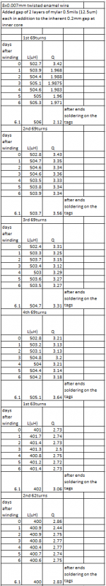
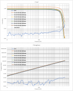
I decided to wind all the six coils (for the 7th order filter) using 2 layers of mylar food wrap.
It ended to be 69 turns for the 502uH and 63 turns for the 400uH. I make the L, Q measurement for some days to see for change due compressibility of the plastic foil and/or relaxation of plastic screw tension.
I’ll report back on this.
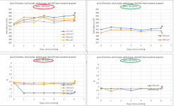
Attachment 1, 2: This is what came out of this test at 1kHz test frequency.
I was thinking that the extra gap due to mylar foil might change from it’s initial value over time but this does not reflect on L and Q values which remained quite stable over a week.
The sharp drop on Q on the 1st coil is due to breaking of two of the 8 0.007mm enamel wires The coil ends were on the air during measuring period. At the last day after the 6th measurement, I properly soldered the leads to the bobbin tags and L, Q values changed slightly (last measuring point on each diagram).
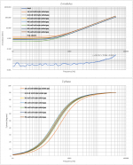
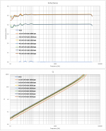
Attachments 3, 4, 5 are impedance sweep results (0-46kHz) on the coils with my E-MU 0404 sound card. Signal level:1Vrms
The faulty coil is to be replaced by another one (the 7th coil at the sweeps).
George
Attachments
Decoupling experiments
As a result of the decoupling discussion my wife got curious and decided to modify her PhiDAC hex by soldering up 5 extra 1uF 0805 X7R caps across the DAC chips, between pins 4 and 5.
The result was quite a surprise to me as I'd expected no difference would be easily heard. Instead we heard a substantially less musical result - we were playing a Beethoven string quartet at the time which I wasn't familiar with. I asked my wife 'Who is this composer?' and was shocked to hear 'Beethoven' as a reply as he's one of my all-time favourites. But the presentation was really rather a turn-off to listen to - strings had lost their usual delicacy.
So then I thought - maybe this isn't about caps per se, its about X7R caps. So next up we changed the X7Rs to Wima 330nF film caps (the kind with 5mm pitch). The jury is still out on how this sounds but one thing we're both clear on - its not an improvement.
So maybe you want to measure on that? Distorsion is jummy you know... Maybe your speakers area bit "dead" and you need a bit of sparkle?
This is what is so hard - talking about one component in a system of unknowns...
The only way forward is individual component technical excellence.
//
This is what is so hard - talking about one component in a system of unknowns...
The only way forward is individual component technical excellence.
//
I wouldn't have a clue what to measure. I've already measured the DAC's distortion (about what the DAC chip's DS leads me to expect) but so far not the amp's. But I doubt the amp has anything to do with it as my wife got similar results when listening with headphones (different amp involved).
Well, this is this sports big culprit - we don't know what to measure. Or with what resolution.
The one that cracks that...
//
The one that cracks that...
//
Hey Abrax: youfinally listen to the advices about avoiding ceramic claa 2... great. Ask wifey to try pps 0808 smd caps from panasonic rubycon or cornel dublier.
TNT...stop to measure too much: it is not an engineering curse to students...be confident with you ears.
TNT...stop to measure too much: it is not an engineering curse to students...be confident with you ears.
Hey Abrax: youfinally listen to the advices about avoiding ceramic claa 2... great.
Looks like a textbook case of confirmation bias 😀 I still have a class II ceramic in circuit.
Try and make an abx surprise to your wife...let theexperment decide if it pass or not the bias text book bias...
In some circuitries. Swapping x7r by pps at iso inductance is often hearable for thebest but not always...depends on the whole acoustic.
In some circuitries. Swapping x7r by pps at iso inductance is often hearable for thebest but not always...depends on the whole acoustic.
Try and make an abx surprise to your wife...
ABX with what as A and what as B?
Incidentally hadn't you said many months ago that you were staying away from this thread in future? What changed your mind?
- Home
- Source & Line
- Digital Line Level
- lingDAC - cost effective RBCD multibit DAC design