Was the NHB-108 not so good, after all?
It is clearly limited in power, especially with difficult speakers. Bass is nothing to write home about, even compared to very cheap amps.
Is it possible to selectively improve these areas without spoiling the good bits is something i don't know. The 458 sounded good to me but i have never heard it in the same system as a 108.
If the 108 series 2 experiment turns out unsuccessful it won't be a big disappointment. Have built dozens of unsuccessful amps in the past 😀
Indeed, given that the first reviews indicated tube like sound, I never did construct this to sound like a Krell with a 500+ damping factor... thus I use it in a biamp set up where this powers the mids/ highs and an old Kenwood M2 powers the bass (it had high NFB and 1000 damping factor ), I'd be hard pressed to find a solution that sounds better for this amount of money. I get good tight bass and soft warm sounds, this is important for my application (near field listening) . So it all depends how you use it and what the application is... I would not lug construction material in a Ferrari nor take a nice lady out for Dinner in a Loading Van...
Now only if I could arrest the weird occasional static I hear sometimes... :-D (goes away after the amp is warmed up)
Now only if I could arrest the weird occasional static I hear sometimes... :-D (goes away after the amp is warmed up)
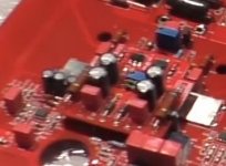
There is a significant number of 8-pin chips on top, no need to search at the bottom. )
Mr Deletraz mentions in the tour that the chips at the top of the 458 were part of the front display function and that they have been moved to a separate card at the back of the Front Display to make room for more power transistors on the 468 MB and for serviceability reasons! That part of the card probably got very warm..
That is the reason I mentioned only the ICs at the bottom/input side of the MB.
Last edited:
At some point in the video Hervé shows the bottom part of the "old" board and the number of power transistors (TO220 and TO-3P) do not match the "Hungarian schematic".
There are two ТО220 parts close to each other and far from the rest, which could be the power supply regulators for the protection circuit, but what about the rest?
PS: The daughter board is also a big mystery. Could it be the voltage amplification part? But why put it on a separate board, hmm?
There are two ТО220 parts close to each other and far from the rest, which could be the power supply regulators for the protection circuit, but what about the rest?
PS: The daughter board is also a big mystery. Could it be the voltage amplification part? But why put it on a separate board, hmm?
Those are not TO220, if you look carefully you will see they are 5-pin devices: 3 altogether. The Hungarian schematic lives on 🙂
The daughter board could carry a BAL > SE converter as this leaves the option for a potential upgrade
The daughter board could carry a BAL > SE converter as this leaves the option for a potential upgrade
The Hungarian schematic lives on 🙂
Speaking of which, did your boards arrive? I am so tempted to try it, but will wait until you hear it first 😀
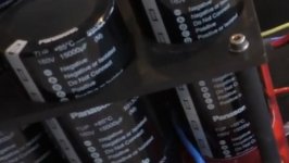
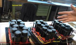
Tons of electrolytic capacitors in 468
Correction: The 468 has 10 Panasonic 15.000uF 100V 85C electrolytic capacitors, mainly because the Chinese market demands tons of them, according to Mr Deletraz 🙂
And they are mounted on a circuit board placed over the MB, close to the power transistors. No more gilded metal crowbar.
Correction: The 468 has 10 Panasonic 15.000uF 100V 85C electrolytic capacitors, mainly because the Chinese market demands tons of them, according to Mr Deletraz 🙂
And they are mounted on a circuit board placed over the MB, close to the power transistors. No more gilded metal crowbar.
Attachments
Last edited:
Maybe...There is also that little daughter board in the 458 on top of the supercaps for which i have no explanation. It looks like it could be a regulator for the input, only there are no sensible PS connections.

5pin voltage regulators:

5pin capacitors in power supply ( 10pcs ):
Panasonic T-UP Series 15.000uF 160V - ECEP2CP153GA
in older models:
CDM Cornell Dubilier 382LX Series 15.000uF 160V - 382LX153M160B102V
Yes, it is certainly a possibility and explains the power resistors. But is the effort worth it for just the input pair?
What is your take on the balanced convertor?
What is your take on the balanced convertor?
Ok, 160V.Panasonic T-UP Series 15.000uF 160V - ECEP2CP153GA
Which means the DC operating voltage over the power transistors is well over +- 100/120V?
The rectifier bridge on top of the lower part of the board + the regulator underneath the board is for a second, lower supply voltage for the input IC's because the very high DC voltage over the output transisitors cannot be regulated down to 5V?
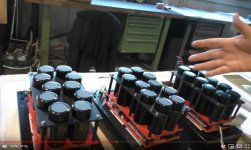
And six large wirewound high power resistors mounted on the separate board along with a heavy duty rectifier (same type as in NHB-108) bridge slow down the current scrambling into those 10X15.000uF electrolytic capacitors when powering up?
Last edited:
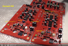
New daughter card
I just noticed a new daughter card inserted between the MB and the capacitor board.
Maybe Mr Deltraz meant this is where they put the 468 electronics for supplying info to the Front Display panel/moved it from the top of the 458 MB?
I just noticed a new daughter card inserted between the MB and the capacitor board.
Maybe Mr Deltraz meant this is where they put the 468 electronics for supplying info to the Front Display panel/moved it from the top of the 458 MB?
Attachments
The 458 MB obviously has some IC's in the input stage.
Why aren't there any in the Hungarian schematic diagram?
Or am I missing something?
Shany's schematic is representing just the amp. Not the Bal input, or any of the auxiliary circuits.
Ok
BTW, the rectifier bridge on the right side of the bottom of the MB is fairly large. It looks like something similar to a BU6-04F. Maybe it supplies driver transistors, not just IC's?
BTW, the rectifier bridge on the right side of the bottom of the MB is fairly large. It looks like something similar to a BU6-04F. Maybe it supplies driver transistors, not just IC's?
After Peter drew my attention to the pin numbers of TO220 devices I took another look at the video.
My guess is the two 5-pin devices next to each other are the PS regulators for the protection/monitoring circuit, while the separate one is the +5V regulator for the display logic.
My guess is the two 5-pin devices next to each other are the PS regulators for the protection/monitoring circuit, while the separate one is the +5V regulator for the display logic.
- Home
- Amplifiers
- Solid State
- Dartzeel amp schematic - build this?