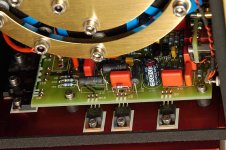
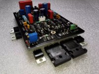
The Chinese two pair version is just the version 1 pcb with two pairs at the output (so not a ver2 circuit, but still ver1...). Look at the Ver2 pcb, you'll see there are a lot less transistors around the board than the ver1. Analog_sa came out with a ver2 possible schematic, based on what we could see on Dartzeel computer screen capture from their factory tour video, and what we can see of the Ver2 pcb. So our ver2 pcb is still just a guess, and a prototype to try out. The Spice simulation looks fine though. I already shipped a few ver2 pcb, and Analog_sa made his ownpcb based partially on my own layout. We will have to wait for the Ver2 builders to report of this new approach...
Attachments
Ok, I see, from the short Matej Isak factory tour. Let's hope that screendump is not just Obfuscation by Mr Deletraz 🙂
Please check Michael Fremers tour on YouTube as well to see if you can pick up some more "secrets". They are discussing the 458 and the 468. But if it is true that the NHB 108 model 2 is a "light" version of the 458 then I guess you may find some interesting info from this film?
YouTube
I was thinking about your soft start and speaker protection circuit, for example.
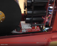
In the 458 they seem to use large resistors ( around 26 minutes) to stop the inrushing current to the electrolytic capacitors. Any idea on that?
I am looking forward to more progress reports on yours and Analogs builds, very interesting.
Please check Michael Fremers tour on YouTube as well to see if you can pick up some more "secrets". They are discussing the 458 and the 468. But if it is true that the NHB 108 model 2 is a "light" version of the 458 then I guess you may find some interesting info from this film?
YouTube
I was thinking about your soft start and speaker protection circuit, for example.
In the 458 they seem to use large resistors ( around 26 minutes) to stop the inrushing current to the electrolytic capacitors. Any idea on that?
I am looking forward to more progress reports on yours and Analogs builds, very interesting.
Last edited:
Looking at my pile of 1302/3281 from mouser, digikey, newark and arrow.Do you know all 1302/3281 are fakes. They have not been done since 2003.
 Realy? Maybe you should specify what exactly is obsolete 😀. Motorolla's 1303/3281 stop being produced long ago, that is correct. Instead Onsemi picked up the fallen torch 😉 So today are produced MJL3281/1302 in TO-264, MJW3281/1302 in TO-247, NJW3281/1302 in TO-3P-3L and NJL3281/1302 in TO-264-5 (with diode on a die) some of the indexes with series above, mostly non ROHS, are obsolete so need to pay attention when ordering (example: MJL1302A is obsolete but MJL1302AG is still active)
How is the build of your new card/design, Version 2, going?
The boards were shipped 3 weeks ago...Currently being delayed by the postal services. These didn't work too well even during peace time and have totally collapsed among the Covid hysteria. My fault for not choosing DHL.
Looking at my pile of 1302/3281 from mouser, digikey, newark and arrow.
I am glad you are correcting me. Something I read on a site but I must have got it wrong.
26 minutes? That's just crazy. Seconds is more then enough.
They are showing the resistors @26 minutes into the film, and forward..
Fremer Dartzeel Factory Tour
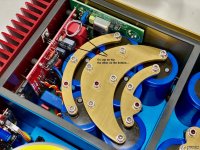
Approx 40 minutes into Michael Fremers factory tour they are showing retired 458 motherboards that are replaced by 468 MBs.
YouTube
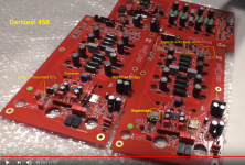
Mr Dartzeel says they added more output Power Transistors to the 468, removed/moved the Display electronics function from the MB onto a separate board behind the front display.
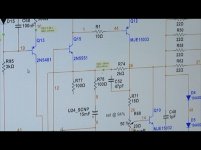
On this screendump from the tour I marked some components.
It seems like the 458/468 is a total departure from the design ideas of the NHB-108.
IC input stage, two supercaps, tons of output power transistors, 6 large (Panasonic) electrolytic capacitors mounted on a separate board on top of the MB (no crowbar) 6 large resitors to slow down? the current rush when 6X22.000uF capacitors charge.
Dental! silver wire as conductor to input stage 🙂
Approx 40 minutes into Michael Fremers factory tour they are showing retired 458 motherboards that are replaced by 468 MBs.
YouTube
Mr Dartzeel says they added more output Power Transistors to the 468, removed/moved the Display electronics function from the MB onto a separate board behind the front display.
On this screendump from the tour I marked some components.
It seems like the 458/468 is a total departure from the design ideas of the NHB-108.
IC input stage, two supercaps, tons of output power transistors, 6 large (Panasonic) electrolytic capacitors mounted on a separate board on top of the MB (no crowbar) 6 large resitors to slow down? the current rush when 6X22.000uF capacitors charge.
Dental! silver wire as conductor to input stage 🙂
Attachments
Last edited:
Fremer Dartzeel factory tour
Mr Deletraz also mentions they replaced the input balance transformers (of CTH 8550) with ICs.
Maybe input balance IC are at the bottom of the NHB-458 boards?
Mr Deletraz also mentions they replaced the input balance transformers (of CTH 8550) with ICs.
Maybe input balance IC are at the bottom of the NHB-458 boards?
IC input stage
How did you figure this one out? 😀
Dental! silver wire as conductor to input stage 🙂
Yup. Why pay big bucks for expensive wire when a friendly dentist lives next door? 🙄
Seems like some of out favourite manufacturers' feet are very firmly grounded.
Mr Dartzeel's private system consists mostly of crappy old components no self respecting audiophile would touch with the proverbial 10 foot. One thing he isn't is gullible.
Similarly with the system we see at the home of Mr Pass: the only audio items with a serious retail sticker are the ones he manufactures 😀
I don’t know how the rest of me personally in this version of the darts are not interested, 108 and no more, but good luck to everyone in the construction.🙂
How did you figure this one out? 😀"
Mr Deletraz also mentions they replaced the input balance transformers (of CTH 8550) with ICs.
Maybe input balance IC are at the bottom of the NHB-458 boards? SSM2141?
What do you think those ICs are?
Similarly with the system we see at the home of Mr Pass: the only audio items with a serious retail sticker are the ones he manufactures 😀
Who is Mr Pass?
Last edited:
I don’t know how the rest of me personally in this version of the darts are not interested, 108 and no more, but good luck to everyone in the construction.🙂
Agree it's not worth it.
There is much better alternatives out there with much better resolution and special according to dynamics.
Maybe input balance IC are at the bottom of the NHB-458 boards? SSM2141?
There is a significant number of 8-pin chips on top, no need to search at the bottom. The SSM2141 is not really suitable as it has differential outputs - unneeded in this application. Any number of ICs can be used here, from INA types to simple opamps. Perhaps not an ideal solution but neither were the cheap transformers in the 108. I guess all the Dartzeels sound better through the single ended inputs.
Who is Mr Pass?
You should ask this in the Pass forum 🙂
I any event there are some IC's at the input part of the NHB-458 MB, regardless which function they may have. And a ton of output power transistors.
A total departure from the NHB-108 design philosophy.
Was the NHB-108 not so good, after all?
A total departure from the NHB-108 design philosophy.
Was the NHB-108 not so good, after all?
Last edited:
The 108 is what put Dartzeel in the map. We can bicker all we want, but with all it’s flaws, it did sound soft and warm. ( at least my Chinese clone does 🙂
If I need an amplifier with more power (although hardly) I will just sell this one and buy another one.:ДThere is much better alternatives out there with much better resolution and special according to dynamics.
Last edited:
And mine too😉The 108 is what put Dartzeel in the map. We can bicker all we want, but with all it’s flaws, it did sound soft and warm. ( at least my Chinese clone does 🙂
- Home
- Amplifiers
- Solid State
- Dartzeel amp schematic - build this?