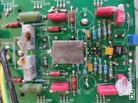
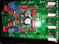
Problem with the supercapacitor which needs to be replaced.
Bypassing it has done the trick for now.
What supercap? Sorry my version does not have one. Is this a DC blocker placed at the output or something in the FB loop or input?
It is the B version of the 108, where one side of the 360R resistors are lifted and grounded through a supercap for AC thus reducing the DC gain. Much to my surprise the supercap's esr had gone up through the roof by a hundred ohms or so. They appear well sealed but contantly elevated temperature apparently dries them out. There is no lifetime data in their specs anyway.
Could I get some advice/comment on electrolytic capacitors for the power supply, please?
Would two of these be a good choice?
High Quality 6* 10000uF / 80V Two Parallel Amplifier Power Supply Board Filter | eBay
(I will not try to emulate the crowbar design, I am only looking for good function at a reasonable price)
Or these?
4*10000uF/100V high quality power supply board for power amp DIY | eBay
What to look for when selecting capacitors for a power supply?
Should they be specified for 105C?
Last edited:
I will use the DC servo and not that "Supercrap Cap"🙄🙄🙄
Both will affect the sound negatively. Hard to say which one is worse. The opamp is less likely to dry out 🙂
I'm not sure. I just followed instructions.maxzimum how is the DC current drift with the supercap bypassed? I am not using any capacitor in the feedback loop and do not have any significant drift.
My Clone was "dancing" +/-200 mv. With Supercap
Weird. The correct way to deal with this is to adjust the offset with the cap shorted out and then remove the short. DC gain without the cap is about 20 and with the cap drops to 2. The input offset appears at the output reduced by a factor of 10 and of course there is some non-input related offset that cannot be reduced but is not significant.
So, before delegating blame to the cap you should examine the situation without a cap. If the inclusion of the cap does not improve it dramatically that means the cap itself is leaky. If the pot appears too jumpy when setting the offset it may be a good idea to use a much lower value like 10-20k.
Not trying to jump to conclusions but this particular board appears to have spent time at Chernobyl during the core meltdown 🙂
My low voltage clone has never had any offset issues at +/-36v. The high voltage one (+/-56v) starts up cold with 140-160mV which settles down to 40-50mV twenty minutes later. The input transistors are in thermal contact with each other and reasonably well matched which helps a little bit. Never felt any need for either a servo or a cap and once every few months check the offset. No Chinese parts anywhere.
I am working on a new empty PCB from scratch. No more fake components from Criminals in China.
It looks like this week my project should go to Production and I will have time to finish tuning the boards... Yay
😀😎The parts look great but this time the circuit seems Chinese 😀
Congratulations🙂It looks like this week my project should go to Production and I will have time to finish tuning the boards... Yay
The parts look great but this time the circuit seems Chinese 😀
How is the build of your new card/design, Version 2, going?
I have tried to find how you (and Algar_emi) found/came up with the schematic for the new card with two pairs of output transistors, but cannot find it.
Besides the physical placement of one the pairs of output transistors, what is the (schematic) difference between your new card and the chinese (original circuit but two pairs of output transistors?) card used by E Saeterdal?
Last edited:
- Home
- Amplifiers
- Solid State
- Dartzeel amp schematic - build this?

