My SP10 was in ok condition cosmetically except for the dents in the start/stop switch
there are several ways to repair the aluminum start /stop cover from dents.
1) bring it to the bodywork done a good hail dent repairer can straighten it up to eliminate the dents if it is not completely destroyed.
2) use a button for technics 1200 and adapt it
3) use the button of the remote SH10R after stripping it down and replace it with the dented button
In my SP 10 Mk2 (I don't have 6) I have adopted all the solutions 1 2 and 3
https://i.postimg.cc/4dDFC01P/F.jpg
ps. the tangential arm is interesting, if it is your project why not illustrate all the processing up to the finished product? It would be very interesting.
Last edited:
How did you manage to get that excellent finish on the platter? It looks amazing!
I removed all the anodization by hand on the edge of the plate and sanded it with several 400-800-1200-1500 water abrasive papers to remove all the lathe work done by Matsushita, then I used 3 different rotating pads and 3 abrasive and polishing pastes to do it in the mirror.
Finally to complete the job I used a polymer car wax to protect from oxidation.
On youtube you will find both the videos and the products I purchased. YouTube
Kit Lucidatura metalli carter forcella marmitta alluminio pulire disco lucidare | eBay
Last edited:

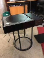
The Image is my SP10 MkII, it was discovered in a shed in a very wanting condition.
The individual who was going to work on the refurbishment,
gave me a Donor Chassis, in a slight better condition than the one I supplied.
I took the Donor Chassis to a Local Vehicle Custom Paint Shop,
and 'Voila' this is what I was returned.
Definitely not original but a nice application of the Paint Job.
I have been using this one for the past year as my go to TT.
It has been out on few visits to the homes of other Vinyl Minded Enthusiasts and has won much favour.
Hi Pitrus,
I repaired the start/stop switch myself very carefully with small hammer from the inside using a bit of hardwood as an anvil. It looks ok now. I do have a 2nd SP10 that is in perfect condition it was used domestically not professionally like this one. I am going to keep it for parts.
The Linear Tracking Arm and plinth was made by me. The plinth was made specifically to take this gantry style tonearm, which was inspired by the Clearaudio TT1. The rail and carriage are not TT1 they were copied from Niffy. I have a Technics EPA100 and this LTA is so superior I will never go back to a pivoting arm. There is a lot of discussion on why the LTA does so well and it is down to the very short and stiff carriage resonant frequency being up the top of the audio band so there is very little audible resonance in the carriage (arm wand).
My build starts about here, it goes over about 30 pages.
DIY linear tonearm
Hi Johnno,
That looks really nice, I like the raw plywood look and the black TT. What is the platter?
The SP10Mk2 is a very good deck and IMO you would need to spend a great deal more to get a TT that would out perform it. I was lucky I stumbled on it late in life. I started my working life as a bench tech for Marantz and had repaired quite a few Marantz DD turntables so I had a huge bias against DD TT's, my first TT was a Linn LP12 which I had for 30years trading it on the worst TT ever a Rega RP8/Apheta.
Wow...I'm going to start reading.
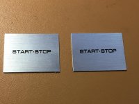
If you go to a trophy maker, they can make up something like this for cents. It is thin aluminium (approximately 0.5 mm) with a sticky peel off backing. The dimensions 38mm x 29mm make it a perfect fit over the Technics button.there are several ways to repair the aluminum start /stop cover from dents.
1) bring it to the bodywork done a good hail dent repairer can straighten it up to eliminate the dents if it is not completely destroyed.
2) use a button for technics 1200 and adapt it
3) use the button of the remote SH10R after stripping it down and replace it with the dented button
In my SP 10 Mk2 (I don't have 6) I have adopted all the solutions 1 2 and 3
https://i.postimg.cc/4dDFC01P/F.jpg
Attachments
Kaneta style plinth and acrylic control box.
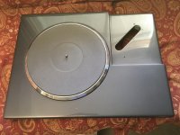
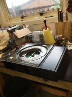
It's been a long term project to re-configure the SP10 mkII with the motor in a custom plinth and electronics and power supply in a separate control box. I have dismantled and serviced about 10 mkII's. This is usually prior to re-finishing the chassis. It has always bothered me how resonant the bare chassis is. It would make a perfect dinner gong. Although a good damped plinth will minimise any negative resonance effects, it is something that I wanted to do something about. I've taken the CV-19 lockdown opportunity to finish off the control box. Nothing fancy about it, just enclosing the old chassis and power supply in one (large) case. The plinth is cast resin/bentonite from a custom mold. The finish is automotive spray paint.
It's been a long term project to re-configure the SP10 mkII with the motor in a custom plinth and electronics and power supply in a separate control box. I have dismantled and serviced about 10 mkII's. This is usually prior to re-finishing the chassis. It has always bothered me how resonant the bare chassis is. It would make a perfect dinner gong. Although a good damped plinth will minimise any negative resonance effects, it is something that I wanted to do something about. I've taken the CV-19 lockdown opportunity to finish off the control box. Nothing fancy about it, just enclosing the old chassis and power supply in one (large) case. The plinth is cast resin/bentonite from a custom mold. The finish is automotive spray paint.
Attachments

Last edited:
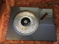
I realised there is very little evidence of the SP10 mkII original, so here are some more images.It's been a long term project to re-configure the SP10 mkII with the motor in a custom plinth and electronics and power supply in a separate control box.
Attachments
Hi Bon, I haven't scrutinised the images at present, but am I right in assuming the original Chassis has been cut in a 'Saucepan Lid', which is the term used when that type of modification happens on a Lenco Chassis.
This is very timely as I have just sent out a Mail early this morning, describing my change of direction in a Plinth Design I am working on, and it looking more like it could be Circular or Ovoid in shape.
I was thinking the SP10 might look a little off on such a design, but this presentation of your design is giving me food for thought
If you go to a trophy maker, they can make up something like this for cents. It is thin aluminium (approximately 0.5 mm) with a sticky peel off backing. The dimensions 38mm x 29mm make it a perfect fit over the Technics button.
does the photo represent the buttons made by a trophy maker?
I know the aluminum button very well, if they are irreparably damaged I recover them from the remote SH-10R 😱😀
https://i.postimg.cc/RVq76cgt/DSCN5413.jpg
I started my working life as a bench tech for Marantz and had repaired quite a few Marantz DD turntables
What do you think of the Marantz TT1000? I'm madly in love with this turntable ... missing from my collection.🙁
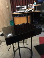
I have not heard of the 'Saucepan Lid' mod before, but I am not a Lenco follower. To clarify, my mod results in two components, the SP10 motor in a separate resin/bentonite plinth, and the motor electronics and power supply in a separate enclosure. The 'lid' in the first photo of my post, is a circular plate covering the hole left in the chassis by the motor and brake removal. I don't know what could be removed from a Lenco, because the motor, drive mechanism are integral to the chassis, in my understanding. Here are some more images of the control box arrangement, which may clarify the design.am I right in assuming the original Chassis has been cut in a 'Saucepan Lid', which is the term used when that type of modification happens on a Lenco Chassis.
Attachments
The photo is of the actual stick-on thin plate that covers the damaged button. It will increase the height by about 0.5 mm. The printing I think is laser cut and is sharper and cleaner than an original Technics button, especially after 40 years and thousands of operations. It depends on the fabricator selection the correct font and size, which should be simple if provided with an original button to copy.does the photo represent the buttons made by a trophy maker?
I know the aluminum button very well, if they are irreparably damaged I recover them from the remote SH-10R 😱😀
https://i.postimg.cc/RVq76cgt/DSCN5413.jpg
What do you think of the Marantz TT1000? I'm madly in love with this turntable ... missing from my collection.🙁
I did get to play with the TT1000, it was made by Micro Seiki, being the apprentice I got to set everything up whenever they were demoing. The one we had in the showroom IIRC had an SME tonearm and it was a really good TT but very expensive. I bought a Linn LP12 which cost me about 4 months wages in 1983 and the TT1000 was more expensive.
I remember bringing my LP12 in and setting up a back to back with the TT1000 no clear winner of this shootout. I think we had a 3300 preamp and 510m power amp cant remember speakers. I had a heavily modified 1060 in my system which I wish I had kept.
12 pin aircraft connector. Connects the 12 wire motor loom to the controller box.Looks good Bon, what cable are you running between the TT motor and electronics?
Attachments
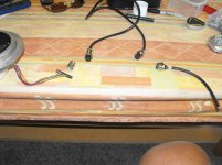
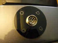
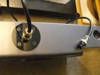
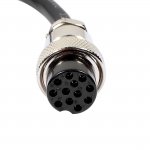
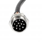
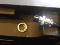
The 12 terminal motor cable tag strip is relocated to the end of the cable on the right, which is inside the control box chassis electronics. The first 12-pin male terminal replaces the tag strip on extensions to the plinth rear.12 pin aircraft connector. Connects the 12 wire motor loom to the controller box.
I have not heard of the 'Saucepan Lid' mod before, but I am not a Lenco follower. To clarify, my mod results in two components, the SP10 motor in a separate resin/bentonite plinth, and the motor electronics and power supply in a separate enclosure. The 'lid' in the first photo of my post, is a circular plate covering the hole left in the chassis by the motor and brake removal. I don't know what could be removed from a Lenco, because the motor, drive mechanism are integral to the chassis, in my understanding. Here are some more images of the control box arrangement, which may clarify the design.
Hi Bon
Now I have seen the innards of the Plinth, I can see how the design has come together, still a very nice workmanship to be seen
A enquiry was made about the Platter on my SP10, at present it is concept idea, the design of the Phosor Bronze Platter is to be investigated to see if it can be used on more than one Brand of TT.
- Home
- Source & Line
- Analogue Source
- The Incredible Technics SP-10 Thread