May have been something else wrong then. I've number twenty-something on my bench presently and have never seen that type of behavior.
Hi JP,
That's what I initially assumed and spent another couple of hours looking for other faults, quite easy to envisage due to the state of the SP10, and I hadn't repaired a DD TT since I left Marantz which is a long time ago, but I had repaired a lot of old mainframe disk drives and when the heads were replaced readjusting sometimes required multiple iterations of the adjustment. I don't know if you are old enough but large disk drives (40Mb with 4 x 12"platters) had replaceable heads.
Initially when I adjusted the period at 33 then 78 switched back to 33 and it was not locked, which is why I looked for other issues, not having experience with the SP10, other than T1 being at the limit of adjustment everything looked good. So I re-adjusted 33 then 78 period 3 times and it came in good. And no it's not a bad pot I checked that and went through this again maladjusting the period
Last edited:
We’ll see. Just found the last (I hope, but probably not) bad transistor in the second one so it’s running again. No chance to check the waveforms yet but if it runs the same on the app, I’m tossing my phone. 😉
Got an Audio Technica 1503 on the way for that one, better start thinking about a plinth...
Good you got 1 working.
I made a resin/bentonite plinth and it performs extremely well with the SP10 and it's not horrendously expensive, you just need to make a mold.
Hi JP,
That's what I initially assumed and spent another couple of hours looking for other faults, quite easy to envisage due to the state of the SP10, and I hadn't repaired a DD TT since I left Marantz which is a long time ago, but I had repaired a lot of old mainframe disk drives and when the heads were replaced readjusting sometimes required multiple iterations of the adjustment. I don't know if you are old enough but large disk drives (40Mb with 4 x 12"platters) had replaceable heads.
Initially when I adjusted the period at 33 then 78 switched back to 33 and it was not locked, which is why I looked for other issues, not having experience with the SP10, other than T1 being at the limit of adjustment everything looked good. So I re-adjusted 33 then 78 period 3 times and it came in good. And no it's not a bad pot I checked that and went through this again maladjusting the period
Just to assure myself that I wasn't mistaken I just tested this with the unit currently on my bench. At 33 I can take VR102 through to either extreme and the waveforms and phase relationship of S and T do not change one bit.
@Thunders
These are the FG signal and motor drive. There's a hair more movement than usual as I'm leaning on the bench to hold my phone steady for the video and the 'table is inverted. You can get a sense of how sensitive things are by applying drag to the platter.
YouTube
YouTube
Re: test records, I've gone through around a couple dozen to find one or two with a decent W&F track. Additionally I've never met a speed or W&F app that was anywhere near accurate. Speed on this is rather simple - ensure the oscillator is set right and you're good, as everything is divided down from there.
Last edited:
Alright! Thanks guys. Your posts just confirmed my suspicion. Was seeing ghosts after all...
The testrecord might be overkill. Spent yesterday evening listening through a testsetup. No abnormalities. 🙂 PSU runs cool & steady as well as the SP10.
On to the second one now.
If it wasn’t for this thread...
The testrecord might be overkill. Spent yesterday evening listening through a testsetup. No abnormalities. 🙂 PSU runs cool & steady as well as the SP10.
On to the second one now.
If it wasn’t for this thread...
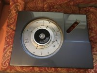
Kaneta style resin/bentonite plinth report
This is a project that I have worked on intermittently for the past 3 years. My previous posts in this thread ##1314, 1488, 1493, 1497, have mentioned various elements of the construction. The final part of re-housing the electronics and power supply in a custom case, has recently been completed.
I have used the SP10 mkII as my main turntable since 1998 and I have had about 10 pass through my hands. The main work I usually performed is the band-brake removal and thrust bearing replacement for worn samples. Then re-plinthing in a cast resin/bentonite plinth.
The naked chassis rings and this bothered me. The Kaneta mod of housing the motor in a high performing plinth and relocating all the other components, seemed like a great idea. It has been brought up in this forum before but did not go anywhere. There is a commercial version by Artisan Fidelity.
SP10 mod plinth a la Kaneta- ideas?
Technics Sp10Mk2 NG — Artisan Fidelity
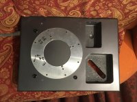
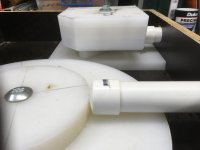
The plinth mold is quite complex, with all the voids and through apertures cast-in-place. This is highly desirable because the cast resin/bentonite composite is not friendly to machine. It dulls cutting tools, produces bad fumes and does not produce a very clean machined surface. The mold construction and inserts are required to be non-stick for easier removal. The dimensions have to be spot-on for the motor/platter void. The bare plinth mass is 28 kg.
The motor is clamped with long stainless bolts through the entire plinth thickness with aluminium plates top and bottom. These plates are tightly fixed to the plinth with multiple fasteners. The massive damped plinth is rigidly attached to the motor in a sandwich arrangement. The plinth is prepped and painted by an auto spray painter professional. This was the most costly part of the project. Materials are inexpensive but you need patience. I glued up an mdf test version in a day. It was used to work out the dimensions of the mold inserts. The cast version takes a week to cure in the mold and weeks of fit and finishing. Definitely not a week-end project.
I will report on my findings of the audio performance in my next post.
This is a project that I have worked on intermittently for the past 3 years. My previous posts in this thread ##1314, 1488, 1493, 1497, have mentioned various elements of the construction. The final part of re-housing the electronics and power supply in a custom case, has recently been completed.
I have used the SP10 mkII as my main turntable since 1998 and I have had about 10 pass through my hands. The main work I usually performed is the band-brake removal and thrust bearing replacement for worn samples. Then re-plinthing in a cast resin/bentonite plinth.
The naked chassis rings and this bothered me. The Kaneta mod of housing the motor in a high performing plinth and relocating all the other components, seemed like a great idea. It has been brought up in this forum before but did not go anywhere. There is a commercial version by Artisan Fidelity.
SP10 mod plinth a la Kaneta- ideas?
Technics Sp10Mk2 NG — Artisan Fidelity
The plinth mold is quite complex, with all the voids and through apertures cast-in-place. This is highly desirable because the cast resin/bentonite composite is not friendly to machine. It dulls cutting tools, produces bad fumes and does not produce a very clean machined surface. The mold construction and inserts are required to be non-stick for easier removal. The dimensions have to be spot-on for the motor/platter void. The bare plinth mass is 28 kg.
The motor is clamped with long stainless bolts through the entire plinth thickness with aluminium plates top and bottom. These plates are tightly fixed to the plinth with multiple fasteners. The massive damped plinth is rigidly attached to the motor in a sandwich arrangement. The plinth is prepped and painted by an auto spray painter professional. This was the most costly part of the project. Materials are inexpensive but you need patience. I glued up an mdf test version in a day. It was used to work out the dimensions of the mold inserts. The cast version takes a week to cure in the mold and weeks of fit and finishing. Definitely not a week-end project.
I will report on my findings of the audio performance in my next post.
Attachments
Great project Bon,
I'll be interested in your opinion on the improvement over a cased SP10. I will most likely go down this path for my next SP10 upgrade. The linear arm was a huge improvement over the pivot.
Did you use poly cutting boards for the inserts?
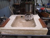
Machining this stuff sucks. I had to do it as mine warped. I used the resin I had (20kg drum of laminating resin) and even though I laid up in 10mm thick pours the plinth still warped. So I machined it flat. That's a 150mm diameter face cutter with HSS inserts and I had to sharpen it 3 times.
I'll be interested in your opinion on the improvement over a cased SP10. I will most likely go down this path for my next SP10 upgrade. The linear arm was a huge improvement over the pivot.
Did you use poly cutting boards for the inserts?
Machining this stuff sucks. I had to do it as mine warped. I used the resin I had (20kg drum of laminating resin) and even though I laid up in 10mm thick pours the plinth still warped. So I machined it flat. That's a 150mm diameter face cutter with HSS inserts and I had to sharpen it 3 times.
Attachments
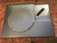
I understand that DIY is more concerned with the technical and constructional issues than subjective reviews, but here are my mains impressions of the pros and cons of the results of the mods. Comparisons are with a mkII (minus band-brake) in a resin/bentonite plinth.
PRO:
1. Presentation is smoother than the stock SP10 mkII.
2. Weightier bass
3. Less noticeable impulse noise (clicks, pops, run in/out grooves)
CON:
1. Switches are less accessible in the separate control box.
2. No brake or strobe
3. Control box is bulky, takes up the same volume as the plinth/motor/platter
4. Platter to plinth clearance is low, limited height for peripheral ring.
I realise that all the PROS are subjective and CONS are operational issues. I can't detect any subjective CONS, the performance exceeds my stock mkII in a resin/bentonite plinth. The smoothness does not seem to be at the price of treble loss. I paid a lot of attention to jazz cymbal reproduction. It was all present and correct.
The tonearm used for the comparisons is the SME IV, cartridges, Ortofon Cadenza Bronze and Audio Technica ART9 and OC9 XSH.
It is well reported that SME V series tonearms are optimised for rigidity and poor plinths and especially floating sub-chassis turntables, can have issues with the energy the tonearm presents to them. I am confident that the mass/stiffness/damping of the Kaneta plinth is dealing effectively with these.
I found that the Kaneta plinth/motor/platter was more sensitive to platter mats than I expected. I settled on a Boston Audio graphite mat (the older type, not the thinner newer version).
Attachments
Hi Warren.
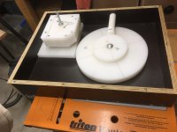
Yikes! Been there, done that. The whole mold construction/casting/curing/removal/trueing/prepping/painting rigmarole, is not for everyone. There were mistakes aplenty.
Yep. Polyethylene from a wholesale kitchen supplies. It turned out 2 layers of 25 mm was just about perfect for the correct motor/platter height.Did you use poly cutting boards for the inserts?
Machining this stuff sucks. I had to do it as mine warped.
Yikes! Been there, done that. The whole mold construction/casting/curing/removal/trueing/prepping/painting rigmarole, is not for everyone. There were mistakes aplenty.
Hi. anyone got the information reguarding how to replace the original logic board logic IC, I beleive they are DTL, instead of the usual TTL? I read somewhere that someone explained by what TTL IC replace the original, and what modification is also necessary to the original circuit, because the circuit uses resistors and caps all over the place and that TTL have different output charactheristics compare to DTL.
I need this info to complete the repair of a SP10Mk2 digital board. It was originally destroyed by a defective 5V supply that has a shorted pass transistor. I was able to get most of the original DTL IC's but I'm missing a few. The table is maybe now 85% fucntionnal, but the speed selection logic is still damaged.
Any help appreciated. Thanks
SB
SP10 Troubles - Page 5 - audio-talk
SP10 fun - audio-talk
Second post mentioned that HCT parts were more stable than LS.
SP10 fun - audio-talk
Second post mentioned that HCT parts were more stable than LS.
On a slightly related subject, has anyone had a go at a modern set of electronics for this motor?
I can get a used motor unit, but the electronics goes for daft money for what it is.
I figure a modern set should cut the parts count by at least half, just replacing that divider chain with a DDS would go a long way, then the rotation detect and start/stop logic is a no brainer to move into whatever toy micro configures the DDS core.
The actual motor control is probably not worth major revision (Well you could go full court on it, but probably not worth the effort), just go for modern parts, darlington transistors for the three output stages, dual transistors for the various long tailed pairs, just the low hanging fruit like that.
Has anyone got a design for this, or do I need to get my pencil out?
It's spinning... in the right direction
The SP-10 gods have finally smiled on me. After two years, I got this thing to finally work! Oh, the hours I have spent working on it, cursing it, to spin in the right direction. It was with a repair tech for a few months and even he couldn't figure it out. Anyway, here is my story, hopefully it can help another unfortunate soul.
I had already done the following things to it:
- New regulated power supply, though I'm still using the original transformer and top board in the PS. The bottom board has been replaced by an LM317 regulator board.
- All new boards in the table itself. This is after I shorted the 32V and 5V lines on one of those long troubleshooting sessions.
None of that seemed to work to get the thing spinning in the right direction. After it came back from the repair tech, it sat for a while as we moved to a new home. I just started looking at it a week ago. Some of my troubles have been documented in the earlier pages of this thread.
The top part of the motor, which comes off, has the magnet being held by a relatively malleable plate. It looks like it is glued to the sub-platter. The previous owner probably used platter screws that were too long causing them to push down on the plate, which then started sticking out at one place around the rim. This had happened earlier and it made the top plate brush against the coils in the stationary motor. Well, after a little bit of pushing and bending with hand, it was now sitting relatively flat against the underside of the sub-platter. Now it was at least spinning smoothly. So, I thought let me give it a try again and viola, it began spinning in the right direction. Checked the waveforms on the scope and they were all locked in with the correct deltaTs. I added the LED-based strobe while I was at it.
I had pushed the plate back last time around because it was brushing, but I didn't undo the whole underside of the sub-platter. This time I did and I could do a better job of bending the plate flat.
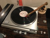
It sounds damn good and easily betters the SL1200. The dynamics are stunning. Feels like there is an order of magnitude less distortion. Just more of everything. Ballsy, gutsy, and rip-roaring are other adjectives that come to mind. Here's a picture of it playing with a DIY version of Pete Riggle's Woody tonearm. The pivot is formed by a setscrew and knitting needle. Sounds bloody amazing.
The SP-10 gods have finally smiled on me. After two years, I got this thing to finally work! Oh, the hours I have spent working on it, cursing it, to spin in the right direction. It was with a repair tech for a few months and even he couldn't figure it out. Anyway, here is my story, hopefully it can help another unfortunate soul.
I had already done the following things to it:
- New regulated power supply, though I'm still using the original transformer and top board in the PS. The bottom board has been replaced by an LM317 regulator board.
- All new boards in the table itself. This is after I shorted the 32V and 5V lines on one of those long troubleshooting sessions.
None of that seemed to work to get the thing spinning in the right direction. After it came back from the repair tech, it sat for a while as we moved to a new home. I just started looking at it a week ago. Some of my troubles have been documented in the earlier pages of this thread.
The top part of the motor, which comes off, has the magnet being held by a relatively malleable plate. It looks like it is glued to the sub-platter. The previous owner probably used platter screws that were too long causing them to push down on the plate, which then started sticking out at one place around the rim. This had happened earlier and it made the top plate brush against the coils in the stationary motor. Well, after a little bit of pushing and bending with hand, it was now sitting relatively flat against the underside of the sub-platter. Now it was at least spinning smoothly. So, I thought let me give it a try again and viola, it began spinning in the right direction. Checked the waveforms on the scope and they were all locked in with the correct deltaTs. I added the LED-based strobe while I was at it.
I had pushed the plate back last time around because it was brushing, but I didn't undo the whole underside of the sub-platter. This time I did and I could do a better job of bending the plate flat.
It sounds damn good and easily betters the SL1200. The dynamics are stunning. Feels like there is an order of magnitude less distortion. Just more of everything. Ballsy, gutsy, and rip-roaring are other adjectives that come to mind. Here's a picture of it playing with a DIY version of Pete Riggle's Woody tonearm. The pivot is formed by a setscrew and knitting needle. Sounds bloody amazing.
Attachments
Last edited:
Great you got the SP10 up and running. DD can be very difficult to fault find as every part of the circuit effects everything else. Unfortunately technicians these days are not trained to the level we were back in the 70/80's.
What's next a DIY linear tonearm?
What's next a DIY linear tonearm?
Funny you should mention that. Had acquired an ET2.5 linear tonearm to go on this table. It is still in its box. Will get that up and running in the coming months.
A great thread that helped give me a push towards an SP10 setup.
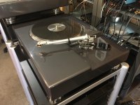
I’ve just finished putting this together.
SP10 MK2 deck, Phonomac Panzerholz Plinth, Puresound Tenuto Gunmetal mat, Fidelity Research FR64fx arm, Orsonic AV101s Headshell, Hana ML cartridge, Bigbottle Audio Spotfire cable.
[emoji4]
I’ve just finished putting this together.
SP10 MK2 deck, Phonomac Panzerholz Plinth, Puresound Tenuto Gunmetal mat, Fidelity Research FR64fx arm, Orsonic AV101s Headshell, Hana ML cartridge, Bigbottle Audio Spotfire cable.
[emoji4]
- Home
- Source & Line
- Analogue Source
- The Incredible Technics SP-10 Thread