Thanks Keantoken,
I can offer one more suggestion, before I depart, follow this thread and youtube videos
SW-VFA-01: Audio power amplifier video series
Put your amp design through his ltspice test bench and sim environment. Maybe even follow his design techniques. To me it is one the best threads to offer this forum in years. Following a seasoned and skilled EE show an amateur like myself the ways to a proper design methodology is rewarding for me at least. In the few videos that have been posted, so far, I would never have figured this out on my own. The design/sim techniques are basically what they do at ADI at the chip level. I just might layout these designs just for the fun of it, not like I need more amplifiers, but it is rewarding to learn from an expert.
Good Luck Rick
Thanks for the kind words Rick!
The goal my thread, and I hope I succeed, is to complement what I know from IC design with what you guys know from Audio and discrete design.
While there is ton of overlap, there are some subtle differences between discrete and IC design beyond the obvious ones like matching, parasitics, and cost. A couple of examples:
Models: In IC design is almost a given that the models you work with are good, and the chances of them being wrong is super low. In discrete this is not the case, you get what you get and you have to deal with it.
Device parameters: In IC, given the accuracy of the models and the maturity of the tools, you can probe a device and the tool will tell you every parameter what you will ever want to know about the device. In discrete you depend on incomplete datasheets. For example, most datasheets do not specify rb for example even though it is a huge contributor of input noise (you can back calculate it from the noise spec IF given though).
Anyway, thanks again for the kinds words! I am hoping to learn quite a few things too.
Best, S!
Last edited:
Yes, Rb is a big one but not just for noise, also for RF behavior. A lot of simulated circuits end up oscillating on the bench because a transistor model omits Rb. Rb is just as important as Ft or Tf. The difference is that it's usually impossible to extract from the datasheet because the noise figure spec is usually some mysterious worst-case number far above what is actually typical for the device. Possibly carried over from the original decades old (or more) datasheets so that they can call it the same part?
And aside from that I feel there is still something wrong with our models. For instance I will construct a circuit and even though I've used models that I've tested extensively for accuracy to datasheets and measurements, it still behaves as if it is 2-3x slower than the simulation models. I really wish I had a network analyzer so I could track down the issue.
And aside from that I feel there is still something wrong with our models. For instance I will construct a circuit and even though I've used models that I've tested extensively for accuracy to datasheets and measurements, it still behaves as if it is 2-3x slower than the simulation models. I really wish I had a network analyzer so I could track down the issue.
I think there are two problems:
- BJT Model: LTSpice uses an adapted version (read simplified) of the Gummel and Poon model for BJTs. This model is old. Everyone in industry has moved to Mextram for accuracy (almost 20 years ago).
- BJT parameter completeness: From the LTWiki page (Q Bipolar transistor - LTwiki-Wiki for LTspice) You can see the model is ~60 parameters. The models we use have about ~30 specified for the good ones (the _K), while others have less.
So between these two, I can see why things don't match up. And yes, to a good AC extraction, you need a good s-parameter network analyzer which is not cheap and definitely beyond the budget of any DIYer.
On that vein, Kean, can you post your latest and greatest set of models? 🙂
Thanks!
Last edited:
Maybe a group buy next?
We are going that path once the amp has been properly verified to work and some listening has been done. But if you are eager, we are looking for Beta builders/testers. 🙂
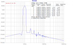
Here is the predicted FFT for 32Vpp into 8ohms (16w) - the profile looks excellent with dominant 2nd order and momotonically descending higher orders. H2 is at -110dB! Of course, in practice the value willl be higher, but the profile is at least predicted to be excellent and non-fatiguing.


Attachments
On that vein, Kean, can you post your latest and greatest set of models? 🙂
Thanks!
My models have gotten a bit messy, with different versions of the same transistor that are so similar I don't really feel they are worth posting. I haven't made a lot of major changes and I can't really do much more with them unless I have a setup that can measure VAF vs Vce. That, and even for those I have curves for I can't fit as well as I would like even with VBIC 1.2.
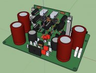
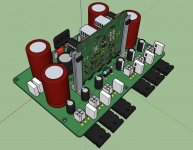
JPS64 is always amazingly fast as usual. Here is the layout so far. We may need to have an off board square puck rectifier mounted to the heatsink. Probably a 4pin maxi Molex could work. I love the custom low inductance MELF feedback resistor mini PCB on removable micro mezzanine from the mezzanine.


Guiderail is Fischer MVS-70.

Super job JPS64!!!
Looks very very super. Thank you!

Edit: JPS64 says the bridge can be mounted underhung to contact the heatsink.
Guiderail is Fischer MVS-70.
Super job JPS64!!!
Looks very very super. Thank you!
Edit: JPS64 says the bridge can be mounted underhung to contact the heatsink.
Attachments
Last edited:
Fantastic work JP!
The mezzanine guide rail is a slick supportive piece 😉
Nice to have the option for under mounting or flying leads for the Mosfets.
The mezzanine guide rail is a slick supportive piece 😉
Nice to have the option for under mounting or flying leads for the Mosfets.
@Gannaji
Sorry, no, but with flying leads no problem to use UMS drilled heatsink.
@Vunce
Thank you!
JP
Sorry, no, but with flying leads no problem to use UMS drilled heatsink.
@Vunce
Thank you!
JP
Does the PCB follow DIYaudio heatsink drilling standard ?
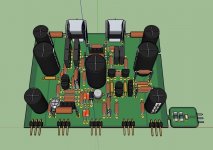
As JPS64 pointed out, the flying leads and Molex quick connects on the main PCB permit mounting of the output MOSFETs anywhere. Including UMS spacing heatsinks from DIYA store, CPU coolers, water cooling blocks, etc.
I would mount the main PCBs on the floor of the amp with the Molex plugs facing the side wall heatsinks. As these have the PSU components it’s like mounting your regular CRC PSU boards in the middle of a chassis. The trafos can be mounted 90deg on edge towards the front of the chassis.
Or in a monoblock chassis, the board could be rotated 90 deg to have the jacks facing the back and have 3 outputs on each side of the chassis.
- Home
- Amplifiers
- Solid State
- Keantoken's Aurum-X 300w Amp with LatFETs