I don't think it was directed at you, you have been quite helpful, so thanks.
And thanks Hugh.
I should say that if anything I am one of the guys that always wants to hijack threads and show my own circuit designs (which I always think are brilliant of course). This inevitably leads to disappointment, as when others don't show the enthusiasm I think they should have, I am left clutching my schematics and my ego slowly drifts toward the furnace vent. So I understand completely this drive to upgrade everything, get the best specs and all that.
Which is why I am okay with this design not having all the upgrades and ticking all the boxes. At the end of the day there is no guarantee that those things are really necessary (although they are really cool). So in a way this amp is a test of my sincerity when it comes to true audio design. If I really want to know how to make good sound, I need to have some respect for the classics. And if it is a bust I will still have learned quite something.
Thanks Keantoken,
I can offer one more suggestion, before I depart, follow this thread and youtube videos
SW-VFA-01: Audio power amplifier video series
Put your amp design through his ltspice test bench and sim environment. Maybe even follow his design techniques. To me it is one the best threads to offer this forum in years. Following a seasoned and skilled EE show an amateur like myself the ways to a proper design methodology is rewarding for me at least. In the few videos that have been posted, so far, I would never have figured this out on my own. The design/sim techniques are basically what they do at ADI at the chip level. I just might layout these designs just for the fun of it, not like I need more amplifiers, but it is rewarding to learn from an expert.
Good Luck Rick
Last edited:
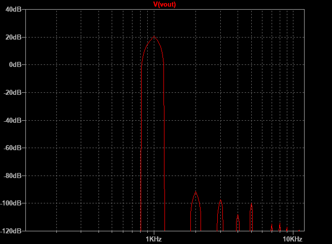
I certainly don’t want to tweak the amp to be lower overall THD, but at the expense of not having a dominant second harmonic and monotonically descending higher order distortion.
One thing that could be improved is to push the 5th harmonic down below the 4th:
One thing that could be improved is to push the 5th harmonic down below the 4th:

The problem here is that while simulation models for Lateral FETs have advanced, they still aren't perfect especially when approaching the rails. I wouldn't guarantee that the spectrum once built will look like that, and if it is real then tweaking the bias current may be all it takes to get rid of it. What does everyone thing about using the -s option Latfets which are color coded for Vgs and meant not to need source resistors?
I like the TTA/TTC transistors and they seem to one of the few available on Mouser. So to improve SOA, should I bootstrap, cascode or switch to MJE340/350 without modifying the circuit?
I like the TTA/TTC transistors and they seem to one of the few available on Mouser. So to improve SOA, should I bootstrap, cascode or switch to MJE340/350 without modifying the circuit?

Nice project!😎
But the SOA of some devices seems to be a bit agressive ...
I would prefer double die Exicons ECW20N20 and ECW20P20
for such high output power.
Also the gate resistors are IMHO too low. In my test sample I have had to increase the gate resistors values to avoid HF oscillations - look schematic here
Have fun, Toni
Nice work on that board - very clean. Not sure how you managed not to get any solder to come through to the TH component side. Sometimes a fillet of solder will improve high current connection, especially on power outputs. Pretty board though.
Hi,
Its quite simple, just need to set temperature of solder station for fit with kinds of solder what you're using, not too hot. Result of that there is only a little bit solder on components side. This thing to ensure the current capacity of connection and highly aesthetics.
Its quite simple, just need to set temperature of solder station for fit with kinds of solder what you're using, not too hot. Result of that there is only a little bit solder on components side. This thing to ensure the current capacity of connection and highly aesthetics.
I like the TTA/TTC transistors and they seem to one of the few available on Mouser. So to improve SOA, should I bootstrap, cascode or switch to MJE340/350 without modifying the circuit?
I would keep the TTC011/TTA006 pair. They are available from Mouser, and there is large stock of both.
Sajti
How can you be sure it will be "best"?
Oh, yes, what a good question!
Since we doesn't have a proper ruler guide there are a lot of thoughts.
My criterios:
1. Mighty and fast OPS with something order of 0.1 THD figures itself and having its own pole frequency not lower than 2-3MHz. There are not so much of. Properly tuned BJT EF3 and dynamically cascoded mosfets, not so much to vote for.
2. VAS with common base last stage, just because you need to properly isolate previous low-voltage stages from huge last stage swing which is beaming through Cob. Ones of pFs for VAS output devices and as high as possible Vceo for Cob degeneration with lowering VAS output capacitance to ground, ksc3503/ksa1381 are the best choise.
3. Inverting connection of the IPS for lowering underestimated common mode-related distortion.
4. As deep as possible feedback depth properly picked from given topology and wrapped around of the OPS for lowering its distortion.
5. Sophisticated frequency correction for keeping overall bandwidth inside OPS freq capabilities under worst case load.
Keantoken and XRK971,
I am interested in read yours amplifier criteria in a more practical way. I and all are full from nonsense and impratical points.
I hope it to be an evolution from old threads to a new, reliable and good soundig amplifier. It will be expensive for sure.
I simulated square wave in 0.93 schematics and I got a terrible result. As it is your thread I will not polute it with my thoughts (Of course I have mine - If you ask, I write it here).
Regards
Last edited:
..... Hopefully we are not too far from a working proto.
Based on the questions Keantoken has, and the valuable input of others, it seems preferable not to rush....
Well the ECX can take 40V at 3A continuous, and they will be driving < 3A peakNice project!😎
But the SOA of some devices seems to be a bit agressive ...
I would prefer double die Exicons ECW20N20 and ECW20P20
for such high output power.
each, I think that puts them a long way inside the SOA box with anything approaching an 8 ohm load, even a fairly reactive one.
A single pair of SJ49/SK135's can give 100W into 8ohms, which is 5A peak.
The lack of secondary breakdown makes a huge difference to robustness and power handling in practice, BJTs usually fail due to secondary breakdown, not over heating, Laterals have to overheat to fail, and thermal protection on the heatsink can make this less likely.
I'd reserve the double-die for when you bridge two of these amps 🙂
Everyone knows that it is very easy to design amplifiers using integrated power circuits. There are many techniques for reduction of distortion that do not generate any result besides spending on parts. And it's very easy to deceive beginners and laypeople with cute PCBs.
To project a good and reliable amplifier is only necessary to apply correctly some well know and old technics. It will not be cheap.
I do not want to hurt Keantoken Ego or rush his project. The idea is just know what he is thinking to do to know if it is interesting to me. He used to share very good ideas with all of us including SIM and Models files.
I do not usually order PCB. I always SIM circuits to find if it is reliable and generate good working results and draw my PCBs after bench tests good results.
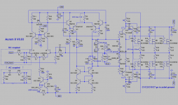
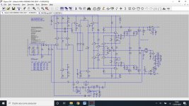
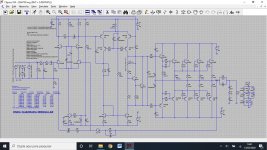
Here I add two commercial amplifier SIM examples:
Hitachi HMA-8500MKII that uses something different servo control but fail in the bias control. It is an old project.
Marantz MA-700 is a new one with a bad compensation arrangement (very high capacitors values). It has compact size, bad heatsink, and small power transformer. It is directed to HT not to quality audio.
Both have fixed first stage bias control as it will define amplifier speed and second stage currents. Note Marantz isolated second stage capacitance using cascode.
In general, the second stage current is usually defined by the final power stage needs.
I also have some projects in my drawer, and do not share it unless some one ask me.
To project a good and reliable amplifier is only necessary to apply correctly some well know and old technics. It will not be cheap.
I do not want to hurt Keantoken Ego or rush his project. The idea is just know what he is thinking to do to know if it is interesting to me. He used to share very good ideas with all of us including SIM and Models files.
I do not usually order PCB. I always SIM circuits to find if it is reliable and generate good working results and draw my PCBs after bench tests good results.
Here I add two commercial amplifier SIM examples:
Hitachi HMA-8500MKII that uses something different servo control but fail in the bias control. It is an old project.
Marantz MA-700 is a new one with a bad compensation arrangement (very high capacitors values). It has compact size, bad heatsink, and small power transformer. It is directed to HT not to quality audio.
Both have fixed first stage bias control as it will define amplifier speed and second stage currents. Note Marantz isolated second stage capacitance using cascode.
In general, the second stage current is usually defined by the final power stage needs.
I also have some projects in my drawer, and do not share it unless some one ask me.
Attachments
Last edited:
- Home
- Amplifiers
- Solid State
- Keantoken's Aurum-X 300w Amp with LatFETs