The Thiele network should not be necessary with a purely resistive dummy load.
Hi Lasse,
You are right, it should be purely resistive if not a bit inductive (wirewound). My thinking was somewhat different.
The LM1875 has tendency to oscillate on the sine-wave peaks. The higher the supply voltage and the lower the load impedance, the worse is this phenomenon. I noticed it from earlier experiments with probably "fake" LM1875s, Chris has noticed it with "genuine" LM1875s.
When Chris puts two modules in parallel, and though the offset figures look good, the oscillation phenomenon becomes worse than when working individually. Of course, if each LM1875 just degrade significantly when put in parallel, paralleling of LM1875 does not serve much purpose. We have to find a way to control this self-oscillation.
I have two initial suspicions concerning the oscillation in parallel. Mutual oscillation where one LM1875 starts oscillation in a neighboring LM1875. Here, the 100pF in the feedback could have an influence because the 100pF connects output to input HF-wise and a neighboring LM1875 can influence the output, in particular much above the audio range.
My other suspicion is poor load sharing above the audio range such that two LM1875 do not see the total load as half loading for each (double the impedance) but one sees close to the full 4 Ohm and starts oscillating as if it was alone. This is where the Thiele network may help as it adds an important impedance in the HF-domain.
I may need to get my "triple" implemented for test soon. I believe such HF-oscillations rely on 2nd order parameters in the LM1875 that are not well included in simulation models.
Our parallel considerations until now have mainly been based on assumptions of the more predictable behavior in the audio range. Thus, "hands on" is probably necessary. If Chris is willing to start with some experiments, I will join when ready and we will work toward getting this oscillation under control.
Your therory sounds interesting, but I doubt that there is actually that much HF energy that has to be shared. Where should it come from, if not from the input? Might be due to self-oscillation of each LM, but again, why?
I could think of insufficient power supply bypassing as another cause. I don't know any "hard facts" about that topic, but I've read something about the wire inductance of the device leads being the culprit. That's why it is advisable to put the bypass caps as close to the device as possible, to keep this inductance small.
Thinking along those lines opens up another can of worms though, with a whole lot of things to try under varying conditions...
After looking at Chris' photos again, the decoupling might actually be a problem. I can see two electrolytics and one film cap on each rail and each module. Elvee always writes that putting capacitors with a ratio bigger than about 10:1 in parallel almost always leads to more problems than it solves. Most of the time it seems that you can simply get away with it, because literally everyone seems to do it. OTOH, why not just try something different? Sometimes less is more.
Try putting the film and small electrolytic on the underside of the board directly to the supply pins of the LM. Use a thick wire for the ground connection. Then try again with the big caps removed from the board, so there's only little capacitance left.
Try putting the film and small electrolytic on the underside of the board directly to the supply pins of the LM. Use a thick wire for the ground connection. Then try again with the big caps removed from the board, so there's only little capacitance left.
The very first important thing is the 0.1μF decoupling caps at GND to V+ and V - of LM1875 leads.
Caps with low ESR at HF.
Caps as close as possible....Soldered on the leads.
Caps with low ESR at HF.
Caps as close as possible....Soldered on the leads.
Hi
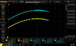
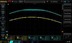
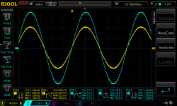
start of oscillating on the top positive sine
pic 9 620mVrms in 1khz at 4,459Rload - about 37,9Watt = 2,91Amps
any additionally test i should do?
chris
Sorry my ignorance if this was explained earlier, but do I assume right if I assume that the yellow scope trace is the input signal?
If so, isn't the oscillation already visible in there, and is not necessarily caused by the 1875 at all???
Hi to all
Thanks for your ideas.
Hi palstanturhin
Yes it looks like the input signal is really not "clean".
I am not really fit...i got a cold 2 days ago...so i need some time to do that...
Thanks for your ideas.
Hi palstanturhin
Yes it looks like the input signal is really not "clean".
I am not really fit...i got a cold 2 days ago...so i need some time to do that...
...but its good to stand up and do some audio😉
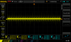
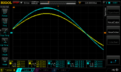
i found that my rigol supply do some high freq. spikes into my environment.
...and i totally forgot the us an additionally 10µF at the input (after the freq.generator)🙄
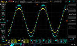
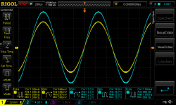
pic 1 -3 are the bad spikes from the psu without 10µF after the freq. generator
pic 4 is with the additionally 10µF...little better
chris
i found that my rigol supply do some high freq. spikes into my environment.
...and i totally forgot the us an additionally 10µF at the input (after the freq.generator)🙄
pic 1 -3 are the bad spikes from the psu without 10µF after the freq. generator
pic 4 is with the additionally 10µF...little better
chris
Attachments

oscillating:
if i remember right from the test of the amp kits from the other thread...here..
https://www.diyaudio.com/forums/chip-amps/341675-ebay-mono-lm1875-kit-29.html#post5966025
post 284 ....
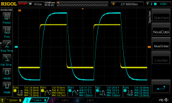
I want to stabilize at square wave input + reactive load C (220nF later with 440nF). I tested some kits with different components - now i use the better parts and get little bit "late" and not so heavy the oscillating. for me its really a behavior of the chip.
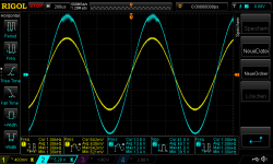
sine wave - still oscillating - no changed values (100pF at the Fb resistor)
pic 1 2x1875_0R47_590mVrms in 1khz at 4,459Rload - everything i fine
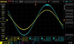
pic 2 + 3 2x1875_0R47_620mVrms in 1khz at 4,459Rload- oscillating
pic 4
2x1875_0R47_660mVrms in 1khz at 4,459Rload - heavy oscillating/clipping
look here: different components - same results = oscillating over 600mVrms at gain of 23 (27dB)
https://www.diyaudio.com/forums/chi...ration-composite-amplifier-9.html#post6013653
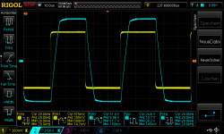
to stabilize under square wave FF helped me to use finally a 100pF at (parallel) the feedback resistor(22k).
https://www.diyaudio.com/forums/chip-amps/341675-ebay-mono-lm1875-kit-36.html#post5995120
now my results: i decided to use the input level under the "critical" level of 600mVrms in = I used for both measurements 580mVrms input with 20kHZ
pic 5
square 580mVrms input with 20kHz at 4,459Rload and 220nf
pic 6
square 580mVrms input with 20kHz at 4,459Rload and 440nf
chris
if i remember right from the test of the amp kits from the other thread...here..
https://www.diyaudio.com/forums/chip-amps/341675-ebay-mono-lm1875-kit-29.html#post5966025
post 284 ....
I want to stabilize at square wave input + reactive load C (220nF later with 440nF). I tested some kits with different components - now i use the better parts and get little bit "late" and not so heavy the oscillating. for me its really a behavior of the chip.
sine wave - still oscillating - no changed values (100pF at the Fb resistor)
pic 1 2x1875_0R47_590mVrms in 1khz at 4,459Rload - everything i fine
pic 2 + 3 2x1875_0R47_620mVrms in 1khz at 4,459Rload- oscillating
pic 4
2x1875_0R47_660mVrms in 1khz at 4,459Rload - heavy oscillating/clipping
look here: different components - same results = oscillating over 600mVrms at gain of 23 (27dB)
https://www.diyaudio.com/forums/chi...ration-composite-amplifier-9.html#post6013653
to stabilize under square wave FF helped me to use finally a 100pF at (parallel) the feedback resistor(22k).
https://www.diyaudio.com/forums/chip-amps/341675-ebay-mono-lm1875-kit-36.html#post5995120
now my results: i decided to use the input level under the "critical" level of 600mVrms in = I used for both measurements 580mVrms input with 20kHZ
pic 5
square 580mVrms input with 20kHz at 4,459Rload and 220nf
pic 6
square 580mVrms input with 20kHz at 4,459Rload and 440nf
chris
Attachments
-
 square 580mVrms input with 20kHz at 4,459Rload and 440nf.png50 KB · Views: 91
 -
 square 580mVrms input with 20kHz at 4,459Rload and 220nf.png47.9 KB · Views: 87
 -
 660mVrms input with 1khz oscillating.png52.6 KB · Views: 94
 -
 2x1875_0R47_620mVrms in 1khz at 4,459Rload_2.png46.9 KB · Views: 77
 -
 2x1875_0R47_620mVrms in 1khz at 4,459Rload.png42 KB · Views: 87
 -
 2x1875_0R47_590mVrms in 1khz at 4,459Rload.png50.5 KB · Views: 290
Last edited:
Hi
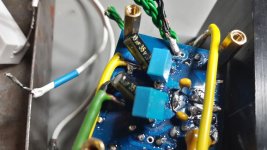
i pick up the idea to use a 0,1µF directly at the V+ - GND -V pins at the LM1875chip. i used the Kemet C322C104K5R5TA - its a X/R ceramic cap.
pic 1 + pic 2
measurements are with 590mVrms in, 600mVrms + 660mVrms - no different to the post 249
maybe it is "lost of time" with this PCB layout to solve this oscillation??
chris
Attachments
-
 2x1875_0R47_660mVrms in 1khz at 4,459Rload + 0,1x7rcap at LM1875.png52.4 KB · Views: 100
 -
 2x1875_0R47_620mVrms in 1khz at 4,459Rload + 0,1x7rcap at LM1875.png52 KB · Views: 96
 -
 2x1875_0R47_590mVrms in 1khz at 4,459Rload + 0,1x7rcap at LM1875.png50.8 KB · Views: 119
 -
 2x1875_0R47+ 0,1µx7rcap at LM1875_2.jpg126 KB · Views: 122
 -
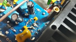 2x1875_0R47+ 0,1µx7rcap at LM1875_1.jpg132.3 KB · Views: 122
Tough luck.Hi
i pick up the idea to use a 0,1µF directly at the V+ - GND -V pins at the LM1875chip. i used the Kemet C322C104K5R5TA - its a X/R ceramic cap.
Well, at least you know decoupling is not the cause of the trouble, it had to be tried.
My favorite caps for this are multy layer chips, giving very quiet rails.
Those X7R are usually multi layer chip ceramics.
Try removing the other caps that you added to the underside of the board.
Try removing the other caps that you added to the underside of the board.
ok.
maybe at the evening i will remove the other caps from the bottom side...we will see...
chris
maybe at the evening i will remove the other caps from the bottom side...we will see...
chris
By "Multy layer chip" I meant multilayer and SMD chip ( chip for Surface Mounting, chip with no lead ).
Ah, okay. Didn't want to be picky, just point out that the through-hole X7R are basically just a SMD MLCC X7R with wires and dipped into epoxy (or whatever), so they should perform just as well. Except for the added wire inductance, of course.
once i built a lm1875 on perf-board (gain 27k+1.2k+22uF; psu decoupling caps only 2x47uF)........had a look at the oszi.......
just before the clipping zone it begins to oszillate similar to your pictures.....
i guess it is the "normal behaviour" of this chip amp........
just before the clipping zone it begins to oszillate similar to your pictures.....
i guess it is the "normal behaviour" of this chip amp........
once i built a lm1875 on perf-board (gain 27k+1.2k+22uF; psu decoupling caps only 2x47uF)........had a look at the oszi.......
just before the clipping zone it begins to oszillate similar to your pictures.....
i guess it is the "normal behaviour" of this chip amp........
OOOH thank you MJF...that what i am thinking too !😀
here are the rusults without my additionally caps under the pcb.
so its 470µF/35V ZLH series from rubicon on the top of the pcb and directly solder at the +V and -V at the chip 1875 -- 0,1µ X7R caps.
--> same result - input signal 1khz
pic 1 590Vrms not ok ---580mVrms input would be better - limiter LED
pic 2 620Vrms not ok
pic 3 660Vrms not ok
pic 4 600mVrms not ok
chris
Attachments
-
 2x1875_0R47_590mVrms in 1khz at 4,459Rload + 0,1x7rcap at LM1875 no other caps at the underside.png51.7 KB · Views: 262
 -
 2x1875_0R47_620mVrms in 1khz at 4,459Rload + 0,1x7rcap at LM1875 no other caps at the underside.png47.2 KB · Views: 261
 -
 2x1875_0R47_660mVrms in 1khz at 4,459Rload + 0,1x7rcap at LM1875 no other caps at the underside.png52.7 KB · Views: 267
 -
 2x1875_0R47_600mVrms in 1khz at 4,459Rload + 0,1x7rcap at LM1875 no other caps at the underside.png46.3 KB · Views: 264
Last edited:
If this oscillation only occurs at clipping and goes away immediately when going out of clipping, I think it is acceptable.
I presume clipping with or without this oscillation makes no audible difference.
I presume clipping with or without this oscillation makes no audible difference.
I agree that very near to clipping and with clipping, the distortion is anyway high and a bit of oscillation on top does not spoil the whole thing. I have had more, even "fake" LM1875 clipping without oscillation and an electrical phenomenon for which I am not sure of the nature and how to control irritates me.If this oscillation only occurs at clipping and goes away immediately when going out of clipping, I think it is acceptable.
I presume clipping with or without this oscillation makes no audible difference.
- Home
- Amplifiers
- Chip Amps
- LM1875 in parallel configuration and used in a composite amplifier.