Here is another discussion about ferrite cored inductors: ferrite-cored output inductor on a class AB amp?
Here are some measurements with different solid core materials in a Class D amp: Selecting the right inductor for ultra-low distortion Class-D audio amplifiers - Analog - Technical articles - TI E2E support forums
In Class D the inductor currents are probably somewhat higher than in a Class AB amp, so I suppose that the negative effect of core saturation (and thus reduced inductance) would be more pronounced in Class D.
Here is another discussion about ferrite cored inductors: ferrite-cored output inductor on a class AB amp?
.........................................................
A very relevant thread with participation of very skilled people. The best (no risk that ferrite creates distortion) is a full air-coil with the damping resistor located outside of the coil. Many of the arguments point to that a ferrite rod should have little effect on distortion but nobody in that discussion is really sure.
We hardly get better advice today. I will specify 2.2uH and leave it as an individual choice if a full air-coil is found. The 10 Ohm is not disputed.
Many thanks for the link.
Sorry, I misunderstood.
As you say: check the supply voltage rails for asymmetry when loaded, check the output offset without input signal and take the output to real clear clipping at 1KHz.
NB: Could it be that you have offset your sophisticated oscilloscope screen with a voltage such that what we see is the scope saturating and not the amplifier? Try putting your probes in 1/10th and AC-coupling for a moment to see if it changes anything.
Hi FF
i am very sorry but i have no solution. here are the results:
same configuration as post 208 https://www.diyaudio.com/forums/chi...ation-composite-amplifier-21.html#post6041529
DC offset is without shorted input -5,1mV DC and goes down to 0,0mV. if i shorted the input its the same.
rail set at Rigol lab psu DP832 (30V/ 2x3Amp...180Watt) +/-25V - with amp on + no signal + 8R i got 24,72/-24,73V at the rails directly on pin 5, 3. up to heavy input signal = 700mVrms sweep in 2 seconds fron 10HZ - 35kHZ (15Vrms into 8R = 28Watt) the each rails at this pins are stable = +/- 24,63V so no cap is damaged.
your idea that maybe my resolution or display is maybe not correct is a very good idea- i move the negative rail to the mid horizontal point of the display to see if the same clipping happens -yes its the same so the scope /display is still working.
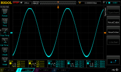
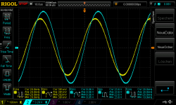
if i start with the signal you can see a good negative sine wave but during 3-10 seconds you can follow that the clipping (cut the sine wave) starts and then it gets small oscillation too.
so up to now no result for me...😉
chris
...............................................
if i start with the signal you can see a good negative sine wave but during 3-10 seconds you can follow that the clipping (cut the sine wave) starts and then it gets small oscillation too.
................................................
Hi Chris,
I know such situations, very frustrating. I picked one of your passages out which I find important for describing the problem.
You have a small period for a start where it works correctly. Then, after 3-10 seconds the negative peak starts collapsing (you see it as clipping) and you notice small oscillations.
It reminds me of my previous experience with LM1875 where my positive peak would collapse.
Try to reduce the supply voltage to +/-18V. Still the same problem?
If still a problem, change the 8 Ohm at the output to 16 Ohm (if possible). Still the same problem?
I guess you have a solid heatsink on the LM1875? Self-oscillation is very temperature dependent.
Thanks FF
yes the heat sink should be not a problem - and the other amp is mounted at the same heatsink and this is working.....look here:
https://www.diyaudio.com/forums/chip-amps/341675-ebay-mono-lm1875-kit-45.html#post6023001
but i recheck this tomorrow
thx🙂
chris
Hi Chris,
I know such situations, very frustrating. I picked one of your passages out which I find important for describing the problem.
You have a small period for a start where it works correctly. Then, after 3-10 seconds the negative peak starts collapsing (you see it as clipping) and you notice small oscillations.
It reminds me of my previous experience with LM1875 where my positive peak would collapse.
Try to reduce the supply voltage to +/-18V. Still the same problem?
If still a problem, change the 8 Ohm at the output to 16 Ohm (if possible). Still the same problem?
I guess you have a solid heatsink on the LM1875? Self-oscillation is very temperature dependent.
Good morning
i did the test with lower supply voltage +8R load:
+/- 20V supply at 360mVrms in 1khz output fine with 7,58Vrms - 7Watt, no other tests
+/- 18V supply at 400mVrms in 1khz output with 8,38Vrms (26,3Vpp)- 8,7Watt but i got on the positive rail the top end oscillating. according to the datasheet its the max because Vout = Vsupply - 10V. if i lower the input voltage to 380mVrms in i still have this oscillating.
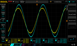
+/- 15V supply at 300mVrms in 1khz output with 6,51Vrms - 18,9Vpp - 5,2Watt - i got again the clipping (cut the top end of the sine) on the positive rail. so its the other rail which is cut now. - pic
for me this LM1875 is "thermal cracked" - maybe it was my fault to cool it not enough with a fan during my test...i don't know
chris
Attachments
Hi Chris,
As the two amplifiers are mounted on the same heatsink BUT THEY ARE NOT CONNECTED with one another through the 0R1 balancing resistors at the outputs (I assume), one amplifier works but the other shows oscillation at certain non-obvious supply voltages, it's time to move on. Replace the seemingly flawed LM1875 with another "genuine" LM1875 and try again.
The 0R1 resistors are pretty small in value. Try 0R5 or so if you want to connect them in parallel again.
Hi Chris,
As the two amplifiers are mounted on the same heatsink BUT THEY ARE NOT CONNECTED with one another through the 0R1 balancing resistors at the outputs (I assume), one amplifier works but the other shows oscillation at certain non-obvious supply voltages, it's time to move on. Replace the seemingly flawed LM1875 with another "genuine" LM1875 and try again.
The 0R1 resistors are pretty small in value. Try 0R5 or so if you want to connect them in parallel again.
Hi FF
thanks for your great support.

.... i will do so.
LM1875 repaired...
Hi
i desolder every componentn and re check them. because of bad quality of the PCB during desoldering i use a new board. as FF wrote i changed all load sharing resisotrs to 0R47 (0,47R) and tested the new board. every thing fine.
pic 1
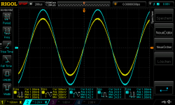
+/-20V supply , DC offset -1,6mV i got into 8R with 480mVrms in (1khz) 9,89Vrms /28,9Vpp out = 12,2Watt- scope looks fine without clipping or oscillating. a bit more and the LM1875 starts slightly to oscillating on the positive sine wave top end.
+/-25V supply , DC offset -1,9mV i got into 8R with 570mVrms in (1khz) 11,9Vrms /35,1Vpp out = 17,7Watt- scope looks fine without clipping or oscillating. a bit more 580mVrms input - the LM1875 starts hard to oscillating on the positive sine wave top end. with 650mVrms in i got hard oscillating and 13,4Vrms / 39,1Vpp into 8R = 22,4 Watt
...now i can re- start to finish my 2 chip paralleling amp🙂
chris
Hi
i desolder every componentn and re check them. because of bad quality of the PCB during desoldering i use a new board. as FF wrote i changed all load sharing resisotrs to 0R47 (0,47R) and tested the new board. every thing fine.
pic 1
+/-20V supply , DC offset -1,6mV i got into 8R with 480mVrms in (1khz) 9,89Vrms /28,9Vpp out = 12,2Watt- scope looks fine without clipping or oscillating. a bit more and the LM1875 starts slightly to oscillating on the positive sine wave top end.
+/-25V supply , DC offset -1,9mV i got into 8R with 570mVrms in (1khz) 11,9Vrms /35,1Vpp out = 17,7Watt- scope looks fine without clipping or oscillating. a bit more 580mVrms input - the LM1875 starts hard to oscillating on the positive sine wave top end. with 650mVrms in i got hard oscillating and 13,4Vrms / 39,1Vpp into 8R = 22,4 Watt
...now i can re- start to finish my 2 chip paralleling amp🙂
chris
Attachments
Good news, Chris.
As you have a gain of just above 22 times, and gain matching would be more difficult with AC-coupled amplifiers, the load balancing resistors need to be larger in value than for the 3.5 times matched gain. 0R47 should be fine. You will evidently loose a bit of output power in the load balancing resistors. If you run your parallel amplifier at full throttle, watch out for the temperature of the load balancing resistors.
As you have a gain of just above 22 times, and gain matching would be more difficult with AC-coupled amplifiers, the load balancing resistors need to be larger in value than for the 3.5 times matched gain. 0R47 should be fine. You will evidently loose a bit of output power in the load balancing resistors. If you run your parallel amplifier at full throttle, watch out for the temperature of the load balancing resistors.
Hi FF
i will be careful.
if i am ready with one side of the amp and I had the hard wire done i will recheck the voltage between the to outputs of the amp to be sure.
thx
chris
i will be careful.
if i am ready with one side of the amp and I had the hard wire done i will recheck the voltage between the to outputs of the amp to be sure.
thx
chris
Coil winding experiments
I tried to make some coils with the wires that I have at hand: 0.75mm and 2.0mm diameter enamelled copper. Aimed for 2.5uH, which calculated to 11 turns for 0.75mm and 15 turns for 2.0mm, both on a 20mm wide piece of plastic tubing as a coil former. Used some Kapton tape to keep the windings together. "Substantial" is a nice word for the huge coils, they're quite heavy actually!
I don't have an LCR meter handy, but I guess they'll all just do fine.
Attachments
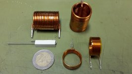
You are a talent. They look really professional. I have ordered some with the ferrite rod inside. If curious enough, you can connect them in series with a known capacitor, find the resonance with your signal generator and calculate the value.
Sorry for the question but I am fascinated by this effort. Is there finalized PCB design? I could not see it within the 233 posts. Could someone fill me in on the status of the project?
Sorry for the question but I am fascinated by this effort. Is there finalized PCB design? I could not see it within the 233 posts. Could someone fill me in on the status of the project?
Not even close to finish yet.
I have just received a couple of proto PCBs to test the 1875+5534 combination alone...
Still a long way to the parallel bridge from here.
Attachments

Hi,
The phases are:
1) Decide on a design for a parallel LM1875 power amplifier (mono/SE configuration).
2) Build the parallel LM1875 power amplifier (mono/SE configuration) and test it.
3) Design and implement (with test) a controlling OP-AMP loop for the parallel LM1875 power amplifier, forming a composite amplifier.
4) Build a second parallel LM1875 power amplifier with a composite amplifier controlling loop. This one with signal inversion.
5) Use and test the two simultaneously in a BTL configuration.
There are initial PCB layouts already on their way but they are meant to experiment with the OP-AMP controlling loop.
At present we are close to finishing 1) above. Yes, it is not going fast but an aim is also to discuss design parameters and trade-offs such that other less experienced members have a possibility to understand why this became the final design and can perhaps themselves make similar designs. On top of that Christmas, New Year, trivial illness etc.......
Last edited:
...paralleling 2 1875 ..test and measurments..
Hi
after illness (again) i do some first test with my left side of 2 1875 parallel.
as good as i can measure with my LCR Meter i choose a resistors for the gain setting as exact as possible and i was lucky from my 30 pcs for each value.
load is 4,459R
DC offset -1,9mVrms
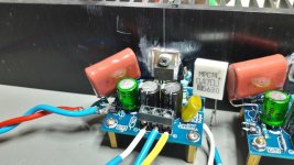
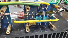
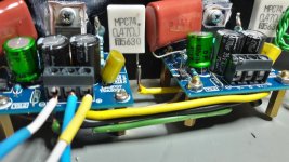
pic 1 +2 are the soldering. i use 1,5mm ^2 stiff cables for the psu and the RG178(coax) for the signal, to connect the amps together with the load sharing resistors 0R47 i use the 1,5mm^2 stiff cable too.
idle with +/-25V rail from DP802 supply 90mA each rail = 2,25Watt each rail
at 400mVrms in @ 4,459R load = about 15-16Watt - consumption is 0,97A = 24Watt each rail
at 600mVrms in @ 4,459R load = about 35 Watt - consumption is 1,37A = 34,25Watt each rail
at 620mVrms in @ 4,459R load = about 38Watt - consumption is 1,41A = 24Watt each rail --> at the top sine wave was oscillating small but between the 2 amps output - so no 0R47 resistor - i got at 600mVrms just 0,3mV !! (yes milli Volt) difference !!
pic 3 400mVrms in 1khz at 4,459Rload - about 16Watt = 1,9Amps
pic 4 400mVrms in 10khz at 4,459Rload - about 15,6Watt
pic 5 400mVrms in 20khz at 4,459Rload - about 14,6Watt
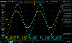
pic 6 600mVrms in 1khz at 4,459Rload - about 35,6Watt = 2,82Amps
pic 7 600mVrms in 10khz at 4,459Rload - about 35Watt
pic 8 600mVrms in 20khz at 4,459Rload - about 32,8Watt
start of oscillating on the top positive sine
pic 9 620mVrms in 1khz at 4,459Rload - about 37,9Watt = 2,91Amps
any additionally test i should do?
chris
Hi
after illness (again) i do some first test with my left side of 2 1875 parallel.
as good as i can measure with my LCR Meter i choose a resistors for the gain setting as exact as possible and i was lucky from my 30 pcs for each value.
load is 4,459R
DC offset -1,9mVrms
pic 1 +2 are the soldering. i use 1,5mm ^2 stiff cables for the psu and the RG178(coax) for the signal, to connect the amps together with the load sharing resistors 0R47 i use the 1,5mm^2 stiff cable too.
idle with +/-25V rail from DP802 supply 90mA each rail = 2,25Watt each rail
at 400mVrms in @ 4,459R load = about 15-16Watt - consumption is 0,97A = 24Watt each rail
at 600mVrms in @ 4,459R load = about 35 Watt - consumption is 1,37A = 34,25Watt each rail
at 620mVrms in @ 4,459R load = about 38Watt - consumption is 1,41A = 24Watt each rail --> at the top sine wave was oscillating small but between the 2 amps output - so no 0R47 resistor - i got at 600mVrms just 0,3mV !! (yes milli Volt) difference !!
pic 3 400mVrms in 1khz at 4,459Rload - about 16Watt = 1,9Amps
pic 4 400mVrms in 10khz at 4,459Rload - about 15,6Watt
pic 5 400mVrms in 20khz at 4,459Rload - about 14,6Watt
pic 6 600mVrms in 1khz at 4,459Rload - about 35,6Watt = 2,82Amps
pic 7 600mVrms in 10khz at 4,459Rload - about 35Watt
pic 8 600mVrms in 20khz at 4,459Rload - about 32,8Watt
start of oscillating on the top positive sine
pic 9 620mVrms in 1khz at 4,459Rload - about 37,9Watt = 2,91Amps
any additionally test i should do?
chris
Attachments
-
 2x1875_0R47_6200mVrms in 1khz at 4,459Rload.png53 KB · Views: 93
 -
 2x1875_0R47_600mVrms in 20khz at 4,459Rload.png50.7 KB · Views: 87
 -
 2x1875_0R47_600mVrms in 10khz at 4,459Rload.png50.8 KB · Views: 93
 -
 2x1875_0R47_600mVrms in 1khz at 4,459Rload.png52.5 KB · Views: 82
 -
 2x1875_0R47_400mVrms in 20khz at 4,459Rload.png52.5 KB · Views: 92
 -
 2x1875_0R47_400mVrms in 10khz at 4,459Rload.png52.7 KB · Views: 90
 -
 2x1875_0R47_400mVrms in 1khz at 4,459Rload.png52.5 KB · Views: 280
 -
 parallel chip amp_2x1875 with 0R47_2.jpg153.2 KB · Views: 268
 -
 parallel chip amp_2x1875 with 0R47_1.jpg151.8 KB · Views: 278
Hi Chris, good initiative.
I am disappointed that you start having oscillation on the tops already when two amplifiers share 2.91Arms.
Do you have the 100pF across the feedback resistors? If yes, try to remove them and see if that helps on the oscillation on the tops.
Do you have a Thiele compensation network between the amplifiers and the load?
Last edited:
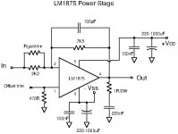
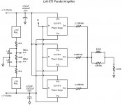
I tried to sum up the last weeks results in updated circuit schematics.
Shown is a version with three LM1875 in parallel. Two can evidently also be used. With two, I suggest to use 0.25 Ohm load balancing resistors.
At a moment in near future we will have to close the LM1875 parallel amplifier design phase and progress to implementation and test. We need not all build the exact same circuit as long as we tell what our results are based on.
Most of us building the circuit will also need to procure some of the parts.
It seems at present that Chris has some oscillation problems that may need further attention.
Attachments
Hi Chris, good initiative.
I am disappointed that you start having oscillation on the tops already when two amplifiers share 2.91Arms.
Do you have the 100pF across the feedback resistors? If yes, try to remove them and see if that helps on the oscillation on the tops.
Do you have a Thiele compensation network between the amplifiers and the load?
Hi FF
it is still the normal schematic without opamp in front of the LM1875 - it is just the ebay kit amp.
yes i have the 100pF across the feedback resistor. i try at the weekend to change it.
No,i do not have a thiele compensation network.
My impression is that the LM1875 gets very easy at it´s max. into the internal heat problems and then start oscillating - the TO-220 housing has its thermal limits. - so its better to use 3x1875and share the current.
chris
- Home
- Amplifiers
- Chip Amps
- LM1875 in parallel configuration and used in a composite amplifier.