I don't think the 1.8K at in+ is a good idea; From the datasheet Ios = 0 typical means it is internally compensated.
http://www.ti.com/lit/pdf/snas524
http://www.ti.com/lit/pdf/snas524
Last edited:
For the LM3886 chip I found some guidance advising 0.7uH in parallel with 10R/(5W). If these are optimum values for our use I cannot tell and any knowledge on the matter is highly appreciated.
Douglas Self wrote something about the "damped output inductor" in his Power Amplifier Design Handbook. According to him, the usual range of the inductor is 1 to 7 microhenries, where the upper limit is due to increasing HF rolloff into 4R or lower loads. The usual resistor is 10R, but can be reduced to as low as 1R, which would still provide adequate damping but reduce overshoot and ringing.
In his Blameless designs, Self uses a "substantial" 6uH air core coil, made of 1.5mm thick enamelled copper wire, 20 turns on 1" (2.54cm) diameter, for a total length of 6cm. "The aim is absolutely guaranteed stability into all capacitative loads". In later designs, as he writes, he cut the inductor in half, for 2-3uH, which should be sufficient.
He also writes about the DC resistance of that coil and how it affects the damping factor of the amp. His advice is thus to make the wire diameter as thick as possible, to keep the resistance low.
I don't think the 1.8K at in+ is a good idea; From the datasheet Ios = 0 typical means it is internally compensated.
http://www.ti.com/lit/pdf/snas524
Many thanks for your comment. Right, the input bias current is specified as "+/-0.5uA, typically 0". I can reduce the value of the resistance at the non-inverting input but I need a certain size if I do offset compensation at that input. Correct, a resistor is not needed but do you see a problem in a resistor being there?
Douglas Self wrote something about the "damped output inductor" in his Power Amplifier Design Handbook. According to him, the usual range of the inductor is 1 to 7 microhenries, where the upper limit is due to increasing HF rolloff into 4R or lower loads. The usual resistor is 10R, but can be reduced to as low as 1R, which would still provide adequate damping but reduce overshoot and ringing.
In his Blameless designs, Self uses a "substantial" 6uH air core coil, made of 1.5mm thick enamelled copper wire, 20 turns on 1" (2.54cm) diameter, for a total length of 6cm. "The aim is absolutely guaranteed stability into all capacitative loads". In later designs, as he writes, he cut the inductor in half, for 2-3uH, which should be sufficient.
He also writes about the DC resistance of that coil and how it affects the damping factor of the amp. His advice is thus to make the wire diameter as thick as possible, to keep the resistance low.
Hi Lasse,
Thanks for your guidance. You really know relevant references.
From Mr. Selfs change of approach, I get the impression that it is not exact science. Let's assume Mr. Self gained more knowledge with time and 2-3uH sounds like a reasonable size. 2.2uH is a standard. I have disassembled a number of good audio amplifiers and the 10 Ohm damping was frequent. I propose 10 Ohm at least for a start.
I found some coils that are probably suited: 5 pieces/8*25 2.2UH 2.0 ligne 20A 8.5 type de barre de cercle inducteurs de filtre a barre magnetique R barre bobine de noyau magnetique-in Inductances from Bricolage on AliExpress
Last edited:
Many thanks for your comment. Right, the input bias current is specified as "+/-0.5uA, typically 0". I can reduce the value of the resistance at the non-inverting input but I need a certain size if I do offset compensation at that input. Correct, a resistor is not needed but do you see a problem in a resistor being there?
Input bias current cancellation discussed here.
Case of internally compensated op amp.
http://www.ti.com/lit/pdf/sbos008
A resistor added to balance the input resistances may actu-
ally increase offset and noise.
Last edited:
Input bias current cancellation discussed here.
Case of internally compensated op amp.
http://www.ti.com/lit/pdf/sbos008
A resistor added to balance the input resistances may actu-
ally increase offset and noise.
Many thanks. At the end of page 7, I found the issue discussed. I will reduce the resistor value.
A silly question. For a single LM1875 I get around 25W into 8 ohm. What do you get at 8 ohm with a parallel LM1875 or is it just being able to drive lower impedance speakers with more available current?
LM1875 with bad negative rail....
Hi FF
Sorry that i am too late to check this failure...
at post 196 you gave me the advice:
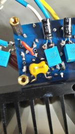
short the NFB cap = 100µF UES (green nichicon) = pic 1
no DC input at the signal input of the amp = i add a 1µF foil cap = pic 2
you remind me that a DC coupling at both = non-inverted and inverted input is a must - that s done by the 22kR at the schoolie´s amp - ebay kit = pic 3...right?
i did the test :
+/-25V supply from my lab PSU - Dc offset with shorted input was nearly 0mVdc, without shorted input i got 1,9mVDC offset. during shorted the input i see that if i touch just the positive input = = signal in the amp is oscillating "loud" - the a output goes up to 5Vrms !!! - ok ..so far...because its the same as i touch with the finger the signal i (+) i think that the trick if you want to see is alive.
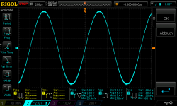
i go up from 50mV input to 240mVrms input and there is the first time you can see the negative rail is going to clipping (cutting the lower sine wave) = pic 4
at 270mVrms in = about 5 Watt into 8R its clear visible the clipping. = pic 5
what i still not understand is what is the difference between my first test (post 170) and then the next day its not working correctly. i suggest a "overload" of the NFB cap with too much power at the ouptut?? - the NFB cap is a 100µF /10V...
😕
chris
Hi FF
Sorry that i am too late to check this failure...
at post 196 you gave me the advice:
short the NFB cap = 100µF UES (green nichicon) = pic 1
no DC input at the signal input of the amp = i add a 1µF foil cap = pic 2
you remind me that a DC coupling at both = non-inverted and inverted input is a must - that s done by the 22kR at the schoolie´s amp - ebay kit = pic 3...right?
i did the test :
+/-25V supply from my lab PSU - Dc offset with shorted input was nearly 0mVdc, without shorted input i got 1,9mVDC offset. during shorted the input i see that if i touch just the positive input = = signal in the amp is oscillating "loud" - the a output goes up to 5Vrms !!! - ok ..so far...because its the same as i touch with the finger the signal i (+) i think that the trick if you want to see is alive.
i go up from 50mV input to 240mVrms input and there is the first time you can see the negative rail is going to clipping (cutting the lower sine wave) = pic 4
at 270mVrms in = about 5 Watt into 8R its clear visible the clipping. = pic 5
what i still not understand is what is the difference between my first test (post 170) and then the next day its not working correctly. i suggest a "overload" of the NFB cap with too much power at the ouptut?? - the NFB cap is a 100µF /10V...
😕
chris
Attachments
-
 LM1875 with bad negative rail_NFB cap shorted.jpg251.9 KB · Views: 355
 -
 LM1875 with bad negative rail_1µF cap at the input.jpg221.2 KB · Views: 376
 -
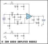 schematic.jpg28.4 KB · Views: 401
 -
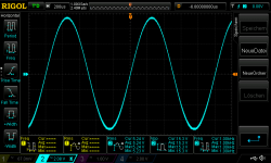 LM1875 with bad negative rail_240mV input.png46 KB · Views: 387
 -
 LM1875 with bad negative rail_270mV input.png44.1 KB · Views: 349
A silly question. For a single LM1875 I get around 25W into 8 ohm. What do you get at 8 ohm with a parallel LM1875 or is it just being able to drive lower impedance speakers with more available current?
Hi rabbitz yes exactly . the paralleling of 2 chips is for 8 ohm (2,1 A rms) not "helpfull"- its ohms law -
e.g. 25V rail --> 21V rail under load --> rms is about = 21*0,707 = 14,8V
14,8V / 8R = 1,88 A rms for 1 chip---> with 2 chip the 14,8V is the same - the load sharing/ temp management is different - but not more power!
at 4 ohm load its possible to handle more current and therefore the the power is nearly (losses are now bigger with more current) double the power at 8R.
look here: post 88
https://www.diyaudio.com/forums/chi...ration-composite-amplifier-9.html#post6013653
chris
Last edited:
A silly question. For a single LM1875 I get around 25W into 8 ohm. What do you get at 8 ohm with a parallel LM1875 or is it just being able to drive lower impedance speakers with more available current?
The purpose with putting more LM1875 in parallel is only to increase the current capability. LM1875 is meant for 6-8 Ohm speakers. With 4 Ohm, it is already at its limits.
With more LM1875 in parallel, it is possible to use BTL configuration and get four times the output power (more than 100W).
When we soon start using such a parallel power stage in a composite amplifier configuration, the THD and SQ can be improved to among the best amplifiers.
Thus, if you know how to connect class AB amplifiers in parallel and with BTL coupling, and know how to design a composite amplifier loop (not terribly difficult is my impression), you know how to make a very high performance amplifier yourself at a moderate cost.
Last edited:
Hi FF
Sorry that i am too late to check this failure...
at post 196 you gave me the advice:
short the NFB cap = 100µF UES (green nichicon) = pic 1
no DC input at the signal input of the amp = i add a 1µF foil cap = pic 2
you remind me that a DC coupling at both = non-inverted and inverted input is a must - that s done by the 22kR at the schoolie´s amp - ebay kit = pic 3...right?
i did the test :
+/-25V supply from my lab PSU - Dc offset with shorted input was nearly 0mVdc, without shorted input i got 1,9mVDC offset. during shorted the input i see that if i touch just the positive input = = signal in the amp is oscillating "loud" - the a output goes up to 5Vrms !!! - ok ..so far...because its the same as i touch with the finger the signal i (+) i think that the trick if you want to see is alive.
i go up from 50mV input to 240mVrms input and there is the first time you can see the negative rail is going to clipping (cutting the lower sine wave) = pic 4
at 270mVrms in = about 5 Watt into 8R its clear visible the clipping. = pic 5
what i still not understand is what is the difference between my first test (post 170) and then the next day its not working correctly. i suggest a "overload" of the NFB cap with too much power at the ouptut?? - the NFB cap is a 100µF /10V...
😕
chris
Hi Chris,
My advise was concerned with testing this LM1875 you thought could be "dead".
You showed a sine-wave curve with asymmetrical clipping which means it is not dead in a normal sense.
While an LM1875 can die (fully) if treated wrong, it is very rare it is permanently harmed "a little". If you suddenly have a smaller mal-performance, it is very often due to the external circuit.
Then, you bring the LM1875 into a very simple configuration (with the NFB cap shorted it is a simple non-inverting amplifier coupling) and test it like that. Still asymmetrical clipping?
FF,
the coils you supposed have a ferrite core. The output inductor in our case should be air cored though, because of the non-linear flux of the core material. Ferrite makes the coil much smaller, but it will add distortion! The best thing is to wind your own coils. Since the absolute value is not very important, you can use whatever wire you have handy and start winding. Use a calculator like coil32.net to check how many turns you need for the diameter you're planning to wind on.
Otherwise you'd have to look out for some pre-made air core coils. I don't know if there are some around with the values we need. Those used in speaker crossover networks are often air cored, but probably with much too high an inductance.
chermann,
did you check your rail voltages with the multimeter while the amp is clipping, preferably directly at the LM's power pins? Maybe something is dropping too much voltage, like a bad fuse or connector, or something is wrong with your psu.
FF,
the coils you supposed have a ferrite core. The output inductor in our case should be air cored though, because of the non-linear flux of the core material. Ferrite makes the coil much smaller, but it will add distortion! The best thing is to wind your own coils. Since the absolute value is not very important, you can use whatever wire you have handy and start winding. Use a calculator like coil32.net to check how many turns you need for the diameter you're planning to wind on.
Otherwise you'd have to look out for some pre-made air core coils. I don't know if there are some around with the values we need. Those used in speaker crossover networks are often air cored, but probably with much too high an inductance.
Hi Lasse,
Admitted, I proposed this choke because it was what I found quickly.
With 2.2uH, the choke impedance matches a 4 Ohm load at 300KHz and an 8 Ohm load at almost 600KHz. In the audio range, the impedance impact is very low.
A coil wound on a ferrite rod corresponds to a coil in a core with a huge air-gap. The much lower but linear permeability of air makes the resulting choke impedance much more linear than with the ferrite alone.
My belief is that the Thiele network is included to avoid self-oscillation above the audio range. That slight distortion high above the audio range is introduced, I assumed to be acceptable.
Pure air-coils are evidently better, at least from a theoretical point of with. Admitted, what I have removed from commercial amplifiers were pure air-coils.
Please let me have your comments to this, my possibly wrong, assumption.
As far as I understand it, the inductance is needed to mitigate the effect of capacitive loads. Usually that is mostly the capacitance of the speaker wire, but there're some fairly arkward speakers out there, electrostats being the most demanding. The capacitive loading will make the amp's negative feedback positive at some point and thus make it oscillate.
What I find interesting is that all commercial Class AB designs that I've seen use air core inductors at the output. I would think that cored inductors would be somewhat cheaper, due to better availability (use in SMPS etc.). Contrary to that, Class D amplifiers seem to use cored inductors almost exclusively. Looks like some measurements are in order to investigate the effects of core material on THD in the usual audio range.
What I find interesting is that all commercial Class AB designs that I've seen use air core inductors at the output. I would think that cored inductors would be somewhat cheaper, due to better availability (use in SMPS etc.). Contrary to that, Class D amplifiers seem to use cored inductors almost exclusively. Looks like some measurements are in order to investigate the effects of core material on THD in the usual audio range.
As far as I understand it, the inductance is needed to mitigate the effect of capacitive loads. Usually that is mostly the capacitance of the speaker wire, but there're some fairly arkward speakers out there, electrostats being the most demanding. The capacitive loading will make the amp's negative feedback positive at some point and thus make it oscillate.
What I find interesting is that all commercial Class AB designs that I've seen use air core inductors at the output. I would think that cored inductors would be somewhat cheaper, due to better availability (use in SMPS etc.). Contrary to that, Class D amplifiers seem to use cored inductors almost exclusively. Looks like some measurements are in order to investigate the effects of core material on THD in the usual audio range.
Hi Lasse,
Thanks for your arguments.
For class D there is the reason that the inductance is in the order of 10-33uH, which will be pretty huge as air-coils. Also, the voltage swing across the chokes is the supply voltage peak-to-peak, which will create quite some electromagnetic noise if the magnetic field is not contained inside a core.
About the ferrite-rod inside Thiele-chokes, I am not sure. Let's see if someone else has an opinion.
Thanks for the explanation guys and it's what I thought. The Overture Design Guide spreadsheet doesn't have the LM1875 so couldn't see the effect.
Hi Chris,
.....
Then, you bring the LM1875 into a very simple configuration (with the NFB cap shorted it is a simple non-inverting amplifier coupling) and test it like that. Still asymmetrical clipping?
Hi FF
sorry to badger you...but this is what i exactly did:
thanks preamp...
i check the rails at the chip....
Thanks for the explanation guys and it's what I thought. The Overture Design Guide spreadsheet doesn't have the LM1875 so couldn't see the effect.
your welcome ...FF took time to explain me that long time ago.🙂
the only chance to get more power from LM1875 into 8 R is a bigger supply voltage:
1
hold the 25V supply really stable -big transformer and cap bank - so it is no huge sag during heavy loads.
2
go up with the rail voltage - keep in mind that the max voltage is +/-30V at LM1875 ...better to keep +/- 27V (please remember my test with the oscillating at that power)
3
bridge the amplifier --> at the same time 1 chip is positive the other is negative (180° phase shift) .....but look at my other post...
the problem is here at the same time e.g. + 14,8V for the upper LM1875 and the other -14,8V = 29,6V into 8R = 3,7 Amp.... this is not possible because the chip´limit is 4A peak = 2,8 rms ( real 2,2A)....yo get a lipped signal - solution is as FF wrote : first paralleling then bridging.
chris
Hi FF
sorry to badger you...but this is what i exactly did:
thanks preamp...
i check the rails at the chip....
Sorry, I misunderstood.
As you say: check the supply voltage rails for asymmetry when loaded, check the output offset without input signal and take the output to real clear clipping at 1KHz.
NB: Could it be that you have offset your sophisticated oscilloscope screen with a voltage such that what we see is the scope saturating and not the amplifier? Try putting your probes in 1/10th and AC-coupling for a moment to see if it changes anything.
my probe at the ouput is done with a differential probe (20x)
- Home
- Amplifiers
- Chip Amps
- LM1875 in parallel configuration and used in a composite amplifier.