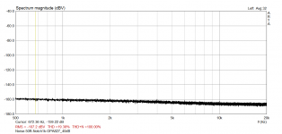
Another test, Victor's 1kHz oscillator, through the passive twin-tee, which gave about 60dB attenuation on the 1kHz, with 10dB attenuation of the 2nd harmonic.
Victor set to 2V, which is +6dBV. Subtract 10dB to account for the attenuation of the 2nd, gives a reference of -4dBV for the analyzer.
That gives the attached graph, with extreme (256x) averaging, no windowing.
Am I doing that right? It does confirm Victors claim that his oscillator is cleaner than -150dB.
I calculate carrier = +6dBV, second harmonic is below -149.05dBV, but second harmonic reads 10dB too low, so the second is less than -139.05dBV. So, second harmonic is at least -145.05dB below the +6dBV carrier.
Still, you can't really tell since the second harmonic "spur" doesn't stick up above the noise floor by at least a few dB because the averages were just power averages. Even if it were just a dB or so away from the noise floor, I would not trust the numeric value. This means the actual 2nd harmonic level is below what can be guaranteed from that measurement.
If you can use synchronous averaging, and sync on Viktor's oscillator, then with 256 averages, you can surely push the noise floor down a good bit and get an accurate level on second and probably third as well. If the fundamental leakage from the notch is not enough to sync onto, there might be some way to Y the generator and feed that to a second channel to sync onto? Or perhaps get less fundamental attenuation from the notch?
This is why a synchronous analog generator is so useful - it prevents the need for jumping through these sorts of hoops.
Has anybody tried to do notch filters with power line transformer sized inductors and
pp capacitors on a medium impedance transmission line?
I had quite good success with this style at 10 MHz. Transmission line transformer
50 Ohm to 400 or 800 ohms, short circuit the transmission lines with crystals with,
say 40 Ohms resistive component and convert back from 400/800 to 50 Ohms.
Lo and behold, 16 dB notches. Good enough to kill the phase noise of a generator
at +- 1.5 KHz.
For audio, 600 Ohms is not uncommon, so the step up and down transformers
are not really needed; it would burn down to just series LC notches with fat components.
When it works at 10 MHz with crystals, it should work at 20 KHz with LC series
resonances.
Maybe the L weighs a pound, but who cares?
Gerhard
Attachments

Last edited:
I calculate carrier = +6dBV, second harmonic is below -149.05dBV, but second harmonic reads 10dB too low, so the second is less than -139.05dBV. So, second harmonic is at least -145.05dB below the +6dBV carrier.
Still, you can't really tell since the second harmonic "spur" doesn't stick up above the noise floor by at least a few dB because the averages were just power averages. Even if it were just a dB or so away from the noise floor, I would not trust the numeric value. This means the actual 2nd harmonic level is below what can be guaranteed from that measurement.
If you can use synchronous averaging, and sync on Viktor's oscillator, then with 256 averages, you can surely push the noise floor down a good bit and get an accurate level on second and probably third as well. If the fundamental leakage from the notch is not enough to sync onto, there might be some way to Y the generator and feed that to a second channel to sync onto? Or perhaps get less fundamental attenuation from the notch?
This is why a synchronous analog generator is so useful - it prevents the need for jumping through these sorts of hoops.
Monte, yes, I think this is an accurate description. In the AP analyzer, you can set the reference for the measurement in dBr. As you noted, +6dBV fundamental, 10dB 2nd attenuation, I set the reference at -4dB. So the values in the graph are referenced to a level of -4dBV.
I turned up de Vicnic to max, around 2.5V which is +8dBV and set the ref at -2dB for the attached, which breaks through the magical -150dB floor ;-).
But agree with you, about the only thing you can say is that the combined source and analyzer distortion is below -150dB. I know that the AP analyzer floor is about -136dB, mainly from the dynamic range limit of the A/D converter. Now with the twin-tee that dynamic range is lowered by at least 50dB, putting it at about -185dB equivalent. Then there is the analyzer preamp gain of +48dB, no idea what the performance of that preamp is, but its input level is around 4mV, output at around 1V.
So far I can not do sync averaging with the Vic oscillator, the AP analyzer cannot be externally sync-ed. But the FFT can be set to track the freq counter which would be the same thing, provided the input fundamental to the analyzer would be large enough, which I don't know. It would be if it was taken after the preamp. It is something I will follow up.
I'll do some more tests today with the Groner opamp see what that gives with 60dB noise gain.
Maybe I can also do some tests with the RC roll-off alluded to by Demian above.
Jan
Attachments
Last edited:
Correction: 'the FFT can be set to track the freq counter ...' should be: the internal notch can be set to track the freq counter ...'
Jan
Jan
With the above setup, I added a Groner/Polak opamp in the chain, set to 60dB noise gain.
See attached. Some conclusions:
- the noise floor, input-referred, appears to lay at -180dB.
- the G/P opamp distortion at 2.5V, 1kHz appears to be below -180dB.
In the original G/P paper, the distortion is shown to be below -180dB, but in a private communication Samuel Groner thought that it actually could be -200dB at 1kHz. I know, this sounds all very incredible and absurd, but so far there is no technical data point contradicting it.
Jan
Attachments
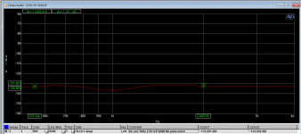
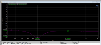
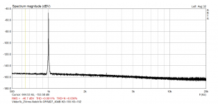
Similar measurement by my sound card.
1.picture - noise level, notch1k input 50R, post-notch 40dB
2.picture - Viktor1k 2Vrms, notch 1k, post-notch 40dB
ARTA in dBV
H1= -46
H2= -155
H3= -152
Notch correction
H2= -155+9 = -146dB
H3= -152+6 = -146dB
Distortion
H2= 6-(-146) = 152dB
H3= 6-(-146) = 152dB
1.picture - noise level, notch1k input 50R, post-notch 40dB
2.picture - Viktor1k 2Vrms, notch 1k, post-notch 40dB
ARTA in dBV
H1= -46
H2= -155
H3= -152
Notch correction
H2= -155+9 = -146dB
H3= -152+6 = -146dB
Distortion
H2= 6-(-146) = 152dB
H3= 6-(-146) = 152dB
Attachments
Last edited:
With the above setup, I added a Groner/Polak opamp in the chain, set to 60dB noise gain.
Jan,
Samuel's plots show a notch that looks like there is no correction at 2H or 3H necessary. Do you know what they are doing?
Similar measurement by my sound card.
1.picture - noise level, notch1k input 50R, post-notch 40dB
2.picture - Viktor1k 2Vrms, notch 1k, post-notch 40dB
ARTA in dBV
H1= -46
H2= -155
H3= -152
Notch correction
H2= -155+9 = -146dB
H3= -152+6 = -146dB
Distortion
H2= 6-(-146) = 152dB
H3= 6-(-146) = 152dB
Very nice! What soundcard did you use? Can you do a sanity check like I did by inserting a defined value 2kHz, for instance?
Jan
Jan,
Samuel's plots show a notch that looks like there is no correction at 2H or 3H necessary. Do you know what they are doing?
I don't know. He probably applied a correction factor in software or test script, or in the post-notch amplifier. He says in his passive filter paper:
The passive filters show a rather wide (low-Q) notch response. Particularly
the 2nd harmonic distortion of the source is thus significantly attenuated
too. A correction factor for each harmonic must thus be applied in post
processing.
Jan
Last edited:
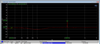
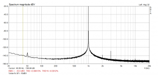
"What soundcard did you use?"
I use modded X-Fi USB HD.
Improving A/D perfromance of Sound Balster X-fi Music (SB1240) - and a Puzzle!!! - diyAudio
"Can you do a sanity check like I did by inserting a defined value 2kHz, for instance?"
I'll try it in the next few days.
Picture, modded XFi line-in at -10dBV driven directly by Viktor1k
Attachments
Last edited:
I've built Samuel's notch filter, measured its transfer function by exciting it with band-limited white noise, and got a very good agreement with the theory, i.e. LtSpice.
In my case, the 2nd harmonic must be corrected by -10dB, the 3rd by -6.
Regards,
Braca
In my case, the 2nd harmonic must be corrected by -10dB, the 3rd by -6.
Regards,
Braca
I don't know. He probably applied a correction factor in software or test script, or in the post-notch amplifier. He says in his passive filter paper:
The passive filters show a rather wide (low-Q) notch response. Particularly
the 2nd harmonic distortion of the source is thus significantly attenuated
too. A correction factor for each harmonic must thus be applied in post
processing.
Jan
Good that makes sense.
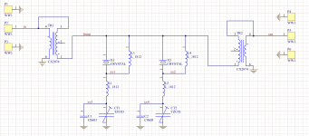
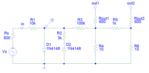
This simple schematic probably can be used for to test the harmonic measurement levels, directly or via the notch filter.
The simulation shows these harmonic levels across the D1 diode rated to the input signal 2,7V RMS (my oscillator max output):
Fundamental -11,6 dB
Second -27,4 dB
Third -27,5 dB
So, the second and third have almost the same levels. These levels can be adjusted more equal with the resistor R2 via the direct measurement, if needed.
The levels at "out1" would be for -80dB lower, and "out2" for -40dB else. Finally, the second and third would be around -147,5 dB.
Attachments
I've built Samuel's notch filter, measured its transfer function by exciting it with band-limited white noise, and got a very good agreement with the theory, i.e. LtSpice.
In my case, the 2nd harmonic must be corrected by -10dB, the 3rd by -6.
Regards,
Braca
Yes I got the same numbers. It seems about standard for a passive twin-tee notch.
I've been playing with a post-notch amp that amplifies the second by 10dB and the 3rd by 6dB, then returns to 'flat'. Not sure it is worth it.
Jan
This simple schematic probably can be used for to test the harmonic measurement levels, directly or via the notch filter.
The simulation shows these harmonic levels across the D1 diode rated to the input signal 2,7V RMS (my oscillator max output):
Fundamental -11,6 dB
Second -27,4 dB
Third -27,5 dB
So, the second and third have almost the same levels. These levels can be adjusted more equal with the resistor R2 via the direct measurement, if needed.
The levels at "out1" would be for -80dB lower, and "out2" for -40dB else. Finally, the second and third would be around -147,5 dB.
So this could be used as a sort of calibration circuit?
Jan
I think yes, but needs to try.So this could be used as a sort of calibration circuit?
Jan
At this moment it is only simulation, but I'll try.Viktor have you tested this or on the simulator?
Jan
- Home
- Design & Build
- Equipment & Tools
- Low-distortion Audio-range Oscillator