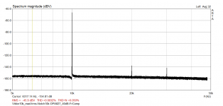
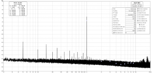
🙂 Better than I measured by myself. The output level is the difference. At maximum output the 10kHz boards with LME49720 typically show H2 little lower than -140dB. The new boards with OPA1656 for app. 5dB better.Viktor10k@2Vrms -> Passive_Notch10k -> OPA827_40dB -> ARTA_H2H3_Compensated
H1 +6dBV
H2 -149dBV
H3 -152dBV
ARTA
FS:96K FFT:128K Wnd:Han Avg:Lin
10k osc (bought Sep 2019) at max output
unbalanced
unbalanced
Attachments
Last edited:
Distortion compensation
If one needs more accuracy, no problem: just follow this procedure.
Cheers,
E.
Indeed, the notch filter is a "bit" more complex. In fact, there many more parameters (compared to a 1st order RC filter). In order to accurately model the behavior around the notch frequency, it turned out that you need quite a lot of samples. But if that many samples are already available, then a relative simple interpolation will also do. So I've tried two interpolation techniques, one based on a 3rd degree polynomial and the other based on a 3rd degree B-spline. It appeared that the latter followed the curvature at the notch more accurately. So, if you don't mind, I stick with B-splines.Edmond: in my distortion compensation project I tried estimating the RC filter component values by nonlinear regression (curve-fitting) of the respective circuit equations to the measured transfer values (amplitude and phase shift), initialized with imprecise values of the circuit components. Worked very precisely. Once the circuit model has the exact component values determined by curve-fitting, you can probe it for any parameter at any condition.
In your case the equations would be more complicated since the filter is a bit more complex,.......
If one needs more accuracy, no problem: just follow this procedure.
Cheers,
E.
Last edited:
Probably still the LME49720 on board.10k osc (bought Sep 2019) at max output
unbalanced
Little trick from my experience. Passive twin T users can make the comparison when they interchange the input/output connections. In theory the filter is absolutely symmetrical, but sometimes in practice, when one of the series capacitors distort, may be a difference. There is more that two times higher voltage across the input capacitor than across second capacitor.
Indeed, the notch filter is a "bit" more complex. In fact, there many more parameters (compared to a 1st order RC filter). In order to accurately model the behavior around the notch frequency, it turned out that you need quite a lot of samples. But if that many samples are already available, then a relative simple interpolation will also do. So I've tried two interpolation techniques, one based on a 3rd degree polynomial and the other based on a 3rd degree B-spline. It appeared that the latter followed the curvature at the notch more accurately. So, if you don't mind, I stick with B-splines.
If one needs more accuracy, no problem: just follow this procedure.
Cheers,
E.
If all you are correcting for are the losses at the harmonic frequencies I would imagine all you need are a few key points. Between the harmonics all there is by definition is noise and spuria. Calculating noise, particularly as in THD+N seems to be quite a different issue. I have several distortion analyzers and software FFT's that just don't agree on the THD+N numbers. Its clear that bandwidth and how the noise is averaged has a lot to do with it along with the SNR of the ADC's.
Little trick from my experience. Passive twin T users can make the comparison when they interchange the input/output connections. In theory the filter is absolutely symmetrical, but sometimes in practice, when one of the series capacitors distort, may be a difference. There is more that two times higher voltage across the input capacitor than across second capacitor.
I'll try that! I also ordered another set of components for a 5kHz twin-tee. The first one had FRP caps and regulkar film R's, I now ordered Wima FKP2 and Holco Rs. We'll see if that makes a difference.
BTW Selecting 6800pF caps for the 5kHz gives you an R value of 4681 which can be exactly made of 2 x 2k + 1 x 681 ohms, all regularly stocked values at Mouser or Digikey ;-)
Jan
Hi Demian,
Cheers, E.
Yes, that is what it is about. Reconstruction of amplitude and phase of the harmonics is rather easy, except regarding the fundamental, which is far more critical. Happily, there are also other means to reconstruct the amplitude of the fundamental.If all you are correcting for are the losses at the harmonic frequencies I would imagine all you need are a few key points.
Very true. But why on earth would someone measure noise figures with a notch filter in the signal path? Notch filters are meant to lower the distortion measurement floor and not noise or THD+N. The latter, at least to me, is an obsolete measure that dates back when measuring THD alone (without noise) was quite involved.Between the harmonics all there is by definition is noise and spuria. Calculating noise, particularly as in THD+N seems to be quite a different issue. I have several distortion analyzers and software FFT's that just don't agree on the THD+N numbers. Its clear that bandwidth and how the noise is averaged has a lot to do with it along with the SNR of the ADC's.
Cheers, E.
Noise & notch filters
At first, I was a bit puzzled by above remarks about measuring noise. Later on, I realized that we were probably at cross-purposes, because you were talking about distortion analyzers more generally, that is, who only work by virtue of a notch filter. Right?
On the other hand, I assumed that we were talking about an "add-on" notch filter as an extension to DiAna. In that case we aren't busy with noise at all, just measuring harmonics at the lowest possible level.
(BTW, DiAna itself doesn't use a notch filter to extract the harmonics. It simply removed the fundamental from the residual digitally).
Cheers, E.
#a little off-topic[...]. Between the harmonics all there is by definition is noise and spuria. Calculating noise, particularly as in THD+N seems to be quite a different issue. I have several distortion analyzers and software FFT's that just don't agree on the THD+N numbers. Its clear that bandwidth and how the noise is averaged has a lot to do with it along with the SNR of the ADC's.
At first, I was a bit puzzled by above remarks about measuring noise. Later on, I realized that we were probably at cross-purposes, because you were talking about distortion analyzers more generally, that is, who only work by virtue of a notch filter. Right?
On the other hand, I assumed that we were talking about an "add-on" notch filter as an extension to DiAna. In that case we aren't busy with noise at all, just measuring harmonics at the lowest possible level.
(BTW, DiAna itself doesn't use a notch filter to extract the harmonics. It simply removed the fundamental from the residual digitally).
Cheers, E.
Vic --
A little off topic but would love to understand your experience with the OPA1656 compared to LME49720. Direct replacement, stability, measurements, etc. I own several of your oscillators can I update them with the OPA1656?
A little off topic but would love to understand your experience with the OPA1656 compared to LME49720. Direct replacement, stability, measurements, etc. I own several of your oscillators can I update them with the OPA1656?
Vic --
A little off topic but would love to understand your experience with the OPA1656 compared to LME49720. Direct replacement, stability, measurements, etc. I own several of your oscillators can I update them with the OPA1656?
Yes, you can replace the LME49720 with the OPA1656. No need to change anything else. As I previously wrote, the difference of the 1kHz performance may be negligible, only noise floor for some dB lower. The older 1kHz boards have no shield across the AGC region. This shield can little help, if you can measure, and your board distortions performance is under -150dB. At the 10kHz you can win app. 5dB in distortions performance, and better load capability. The new boards have also little lower signal across the AGC FET - 30mV p-p instead of 40mV p-p, but if you wish to adjust this, please PM me.
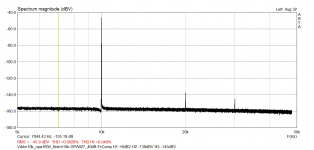
I just replaced LME49720 with OPA1656 in my 10k osc. Confirmed, little better thd and noise.
H1:+8,+9dBV (osc max output, not measured exactly)
H2:-138dBV
H3:-145dBV
(notch h2,h3 compensated graph)
H1:+8,+9dBV (osc max output, not measured exactly)
H2:-138dBV
H3:-145dBV
(notch h2,h3 compensated graph)
Attachments
Last edited:
Does it means H2: -146dB...-147dB?I just replaced LME49720 with OPA1656 in my 10k osc. Confirmed, little better thd and noise.
H1:+8,+9dBV (osc max output, not measured exactly)
H2:-138dBV
H3:-145dBV
(notch h2,h3 compensated graph)
#a little off-topic
At first, I was a bit puzzled by above remarks about measuring noise. Later on, I realized that we were probably at cross-purposes, because you were talking about distortion analyzers more generally, that is, who only work by virtue of a notch filter. Right?
On the other hand, I assumed that we were talking about an "add-on" notch filter as an extension to DiAna. In that case we aren't busy with noise at all, just measuring harmonics at the lowest possible level.
(BTW, DiAna itself doesn't use a notch filter to extract the harmonics. It simply removed the fundamental from the residual digitally).
Cheers, E.
I was talking about analyzers in general and in particular the inability to actually correlate reading from a traditional analyzer to one using FFT or similar techniques. And in more general terms why the FFT noise measurement in about he same band as an analog instrument in many cases seems higher. This is really only relevant when comparing e.g. an AP 555x or Shibasoku 735 to something like an RTX with any of several software packages. I believe some is due to the need to lower the level for lowest distortion but the noise comes up by the reduced level. Its all a difficult conundrum to resolve. And probably meaningless except for number obsessives (distortion nuts). Something I need to consciously disengage from.
I'll try that! I also ordered another set of components for a 5kHz twin-tee. The first one had FRP caps and regulkar film R's, I now ordered Wima FKP2 and Holco Rs. We'll see if that makes a difference.
BTW Selecting 6800pF caps for the 5kHz gives you an R value of 4681 which can be exactly made of 2 x 2k + 1 x 681 ohms, all regularly stocked values at Mouser or Digikey ;-)
Jan
New twin-t, better resistors (Vishay/Dale CMF55), and using the above values. Now none of the harmonics are invisible above the noise.
Wow - who'd have thunk!
Jan
Attachments
After initially troubles with Victor's oscillator and Victor's "witchcraft" finally measurements es it should bee:
2V 1kHz signal without a notch (on RTX6001 30dBV input) exhibits almost no visible harmonics content and THD of -135dB.
Victor 2V on RTX 30dBV input.png
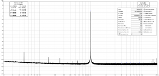
And the same 1kHz signal at max. level-almost 3V, measured with notch on most sensitive RTX6001 input (0,1V), exhibits no visible harmonics. According to Victor, notch harmonics attenuation is app. 9dB for the second harmonic and app. 5dB for the third harmonic, so in the worst case 2H is at app. -156dB and 3H at app. -159dB down.
Victor max with notch on 0,1V TRX input.png
Oscillator was powered with Jan's SilentSwitcher (abused from AutoRanger) and measured unbalanced and unshilded!
It is interesting how mains harmonics content is now also lower than measured before.
Victor, thanks a lot
2V 1kHz signal without a notch (on RTX6001 30dBV input) exhibits almost no visible harmonics content and THD of -135dB.
Victor 2V on RTX 30dBV input.png
And the same 1kHz signal at max. level-almost 3V, measured with notch on most sensitive RTX6001 input (0,1V), exhibits no visible harmonics. According to Victor, notch harmonics attenuation is app. 9dB for the second harmonic and app. 5dB for the third harmonic, so in the worst case 2H is at app. -156dB and 3H at app. -159dB down.
Victor max with notch on 0,1V TRX input.png
Oscillator was powered with Jan's SilentSwitcher (abused from AutoRanger) and measured unbalanced and unshilded!
It is interesting how mains harmonics content is now also lower than measured before.
Victor, thanks a lot
Attachments
That's a very good result! I must try to duplicate that.
In the second graph, how many averages are used?
Jan
In the second graph, how many averages are used?
Jan
- Home
- Design & Build
- Equipment & Tools
- Low-distortion Audio-range Oscillator