I actually think the calculation is more simple than that.....
Using the same numbers:
No notch:
H1 = -6dBV
Harmonics measured with notch:
H2 = -112 after 40 dB amplification
H3 = -115 after 40 dB amplification
-112 what? dBFS? dBV? This is very important to straighten out. If you are measuring this in an FFT window, that would be measured in dBFS. Since you defined the original sine wave to be essentially 0dBFS, then "-112" would be -112dBFS.
These are filter gains, so you do not use dBV, you just use dB, since a gain is a ratio of two levels, the input to the filter and the output of the filter. dBV is the level of a voltage relative to 1V - not appropriate to specify a filter gain.Notch attenuation measured using H2 and H3 test signals:
H2att = -9 dBV
H3att = -5 dBV
Relative to fundamental:
H2 = -143 + 6 = -137 dBc
H3 = -150 + 6 = -144 dBc
I can see that the result is different and that worries me, even though I can't see where I'm doing something wrong😕
If the fundamental into the FFT analyzer is essentially 0dBFS, then the -6dBV factor is not appropriate, since your harmonic levels are measured in dBFS, not dBV. In fact, there should be no dBV in any of your calculations if you have made the DUT drive equal to 0dBFS, whatever voltage that is. You have automatically removed the need for that correction - it is a factor of 0dB relative to the dBFS harmonic measurements.
This measurement with the notch is a tough business 🙂 The source impedance and the input impedance of the notch form a voltage divider. This attenuation is included in the measurement. And makes the reading better! But in reality, the reading is worse. And you have to subtract that in the calculation. Right?As long as the depth of the notch @ H2 and H3 are actually measured in the same circuit, and not table values, I also cannot see why we should correct for input impedance of the notch as this is already included.
You are of course right. I understood the data in the reported example wrongly and the last 6 dB correction is wrong. Nevertheless, the calculations will not bring me to where the others arrived....If the fundamental into the FFT analyzer is essentially 0dBFS, then the -6dBV factor is not appropriate, since your harmonic levels are measured in dBFS, not dBV. In fact, there should be no dBV in any of your calculations if you have made the DUT drive equal to 0dBFS, whatever voltage that is. You have automatically removed the need for that correction - it is a factor of 0dB relative to the dBFS harmonic measurements.
And sorry for the incorrect terminology - I will try to get it right the next time

This measurement with the notch is a tough business 🙂 The source impedance and the input impedance of the notch form a voltage divider. This attenuation is included in the measurement. And makes the reading better! But in reality, the reading is worse. And you have to subtract that in the calculation. Right?
Let's say I have a 1kHz notch.
1) I set up my generator to output a -10 dBV 2kHz signal and my analyser confirms that this is what I get.
2) I put the notch in and now the signal is -19 dBV.
3) This measured attenuation (9 dB) must be the sum of the notch attenuation and the voltage divider attenuation created by the insertion of the notch in my circuit. Right?
Now if I later correct for both the measured attenuation (9 dB) and the calculated voltage divider attenuation I will correct for the latter twice. Right or wrong😕
I dunno what's the problem. My measurement and calculation are valid. The point was to show how to measure distortion down to -150dB when you have -110dB sound card. In my case the limiting factors are the notch and the post-notch amp noise levels.
Last edited:
That's right.Let's say I have a 1kHz notch.
1) I set up my generator to output a -10 dBV 2kHz signal and my analyser confirms that this is what I get.
2) I put the notch in and now the signal is -19 dBV.
3) This measured attenuation (9 dB) must be the sum of the notch attenuation and the voltage divider attenuation created by the insertion of the notch in my circuit. Right?
The shield MUST be used, if needs to measure very low harmonics. The LME49720 opamp circuits are sensitive to high frequency fields. I observed different side effects many times when I used the oscillator board without the shield. We are living in Wi-Fi, radiochannels and mobile world.A housing has only effects on the noise, not on the distortions.
As example, you can see:
My 1kHz old board covered with the good shield - https://content23-foto.inbox.lv/albums/v/viccc/HFeffect/GSh.jpg
The same board without shield in my conditions - https://content23-foto.inbox.lv/albums/v/viccc/HFeffect/WSh.jpg
3cm long antenna with 1V rms 400MHz signal at 5cm distance from the board - https://content23-foto.inbox.lv/albums/v/viccc/HFeffect/400MWSh.jpg
As you can see, the significant second harmonic is observed.
Last edited:
Good to know. Thanks for pointing that out. I have always shielded to block hum and had good results.The shield MUST be used, if needs to measure very low harmonics. The LME49720 opamp circuits are sensitive to high frequency fields. I observed different side effects many times when I used the oscillator board without the shield. We are living in Wi-Fi, radiochannels and mobile world.
As example, you can see:
My 1kHz old board covered with the good shield - https://content23-foto.inbox.lv/albums/v/viccc/HFeffect/GSh.jpg
The same board without shield in my conditions - https://content23-foto.inbox.lv/albums/v/viccc/HFeffect/WSh.jpg
3cm long antenna with 1V rms 400MHz signal at 5cm distance from the board - https://content23-foto.inbox.lv/albums/v/viccc/HFeffect/400MWSh.jpg
As you can see, the significant second harmonic is observed.
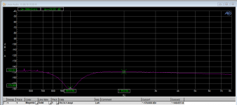
Tested my LKA twin tee today. After I corrected a stupid stuffing error :-(
See attachment. I'm happy - now forward to use it to do great things!
Jan
Unfortunately, the thing has a bit of deviation. Do you use 0.1% resistors and 1% caps?
It's worth mentioning that the notch input voltage should be line level, 1-3Vrms in order to keep the distortion low and not "overload/overheat" the filter. So, if we measure power amp, it's desirable to have low distortion/impedance attenuator at the input of the notch.
NOISE contribution
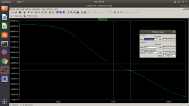
Picture1: SIMed notch output noise
green trace - source impedance 50R
blue trace - source impedance 600R
NOISE contribution
Picture1: SIMed notch output noise
green trace - source impedance 50R
blue trace - source impedance 600R
Attachments
Last edited:
Most of the noise is still generated by the 40dB amp. 0.88uV (bw=20kHz)It's worth mentioning that the notch input voltage should be line level, 1-3Vrms in order to keep the distortion low and not "overload/overheat" the filter. So, if we measure power amp, it's desirable to have low distortion/impedance attenuator at the input of the notch.
NOISE contribution
Picture1: SIMed notch output noise
green trace - source impedance 50R
blue trace - source impedance 600R
Last edited:
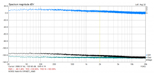
Op-amp based post-notch amp has typical input referenced voltage noise 3-6nV at 1kHz. Consider OPA827, cc 4nV at 2kHz. The preceding notch output noise is 6.5nV, so the combined inp ref noise will be 7.6nV. If amplification is 100x(40dB) then the noise level "going" to the sound card input will be -122dBV at 2kHz. Bellow this level you can't measure H2.
Picture2: noise level measurement
green trace - OPA827_40dB, source imp 50R
black trace - notch filter + OPA827_40dB, source imp 50R
As you can see, the measurement is pretty close to the calculated value.
Picture2: noise level measurement
green trace - OPA827_40dB, source imp 50R
black trace - notch filter + OPA827_40dB, source imp 50R
As you can see, the measurement is pretty close to the calculated value.
Attachments
Last edited:
Unfortunately, the thing has a bit of deviation. Do you use 0.1% resistors and 1% caps?
Yes. What deviation do you mean, from 1kHz?
Jan
Yes, 1007HzYes. What deviation do you mean, from 1kHz?
Jan
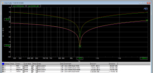
Another test, Victor's 1kHz oscillator, through the passive twin-tee, which gave about 60dB attenuation on the 1kHz, with 10dB attenuation of the 2nd harmonic.
Victor set to 2V, which is +6dBV. Subtract 10dB to account for the attenuation of the 2nd, gives a reference of -4dBV for the analyzer.
That gives the attached graph, with extreme (256x) averaging, no windowing.
Am I doing that right? It does confirm Victors claim that his oscillator is cleaner than -150dB.
Jan
Attachments
can you please tell us AP gain settings
It was on autorange and went to 256x which I think is 48dB.
Edit 48.16dB ;-)
Jan
Jan- Try the low pass filter trick on the output of the Victor oscillator. A cap .25 uf will roll off around 1KHz and have a predictable attenuation and phase impact on the harmonics of the source. It will help separate the source distortions from those downstream. Check with a resistor with the same fundamental attenuation. Obviously at this level the passives need to be exceptional.
- Home
- Design & Build
- Equipment & Tools
- Low-distortion Audio-range Oscillator