r.m.s. power is 50% of peak power, so 25 x 25 / 9 / 2 = 35W
Or put another way r.m.s. power = Vrms^2/R = (Vpeak/√2)^2/R
Yes. I was wrong.
But enough power.🙂 With a load of 4 ohms, the power will still increase.
Last edited:
It is also necessary to reduce the resistors R8, R9.
Why ?
there is no relationship with the supply
if it's to reduce the bandwidth, you better use all specified transistors and a pcb like Michele with ground plate and capacitor on board
all this certainly has an impact on the stability
Last edited:
Why ?
Maybe someone wants to build an amplifier on the IRF1010. Now on j113 - 23 V.
what is the relationship with R8 R9 ?
but to220 case is not suitable for me, you checked the SOA?
but to220 case is not suitable for me, you checked the SOA?
Last edited:
Hi Sébastien,
Changing the values of R8,R9 is a convenient way to adjust the open-loop gain of the amplifier for stability with different gain devices. I assume jpatay reduced R8,R9 for stable operation with the IRF1010E output devices.
The circuit I originally proposed here set R8,R9 = 499 ohms, but this was for a PMOS Vas. Your PNP Vas has more gain, so it may be a good idea to recheck for stability (e.g. using a 10 kHz square wave driving a 1 uF load) and adjust R8,R9 if needed.
Last edited:
what is the relationship with R8 R9 ?
I did not change the values of R8, R9. 470 ohms left.
the implementation is important too
Agreed - stability is not affected by component choice alone, but also by construction technique, layout, thermal management, etc.
yes it is better to increase, I think even increase with mine, but it decreases the stability
I will increase the current. I looked at the datasheet j113: Idss min. - 2 mA.
no.... the fact that it is 2ma on datasheet does not mean that they should be used at 2min.
it is the value that guarantees the constructor....
which is also completely wrong, you never find j113 with idss so low, it misses a 0
it is the value that guarantees the constructor....
which is also completely wrong, you never find j113 with idss so low, it misses a 0
I think you should lower R17/R18 or increase current by selection
How much did you measure when matching?
How much did you measure when matching?
Sébastien,
The translator translated it incorrectly, I did not understand everything.
I wrote earlier: R17, R18, R19, R20 - 270 Ohm. R8, R9 - 470 Ohm.
V2, V3 - 28.5 V. On the capacitor C7 - +26.7 V. On the emitter Q3 - 23.5 V. On the B Q3 - 22.9 V.
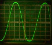
Today I replaced the BD140 with a BC557B (hFE - 250) and installed a small heatsink on them.Excitation at the output of the amplifier disappeared. I turned off the Zobel filter. Square impulses have not changed. Clipping symmetrical.
I will probably stop at this stage.
The translator translated it incorrectly, I did not understand everything.
I wrote earlier: R17, R18, R19, R20 - 270 Ohm. R8, R9 - 470 Ohm.
V2, V3 - 28.5 V. On the capacitor C7 - +26.7 V. On the emitter Q3 - 23.5 V. On the B Q3 - 22.9 V.
Today I replaced the BD140 with a BC557B (hFE - 250) and installed a small heatsink on them.Excitation at the output of the amplifier disappeared. I turned off the Zobel filter. Square impulses have not changed. Clipping symmetrical.
I will probably stop at this stage.
Attachments
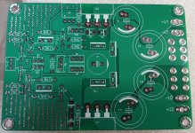
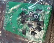
Waiting for a package with 2SA1538 and pcb. Then I will replace the BC557B with 2SA1538.
Once again, thank you to everyone who participated in the creation of this circlotron circuit.
Once again, thank you to everyone who participated in the creation of this circlotron circuit.
Last edited:
very good news, it should change a lot of things
have fun
Yes.🙂
Attachments
- Home
- Amplifiers
- Solid State
- Current feedback Mosfet Circlotron