So you Found irf150n.
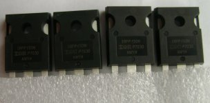
Yes, I found, only such IRFP150N:
Attachments
Yes, I found, only such IRFP150N:
if needed i have to spare.
both IR and vishays
Do you meas them ?
No, there is not much choice, only 4 pieces.
I bought the cheapest transistors.
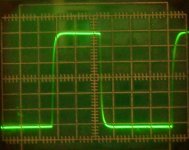
Two channels are already running on the (2SA1360) IRFP150N. C7 - 1 uF MKP Wima. 😉
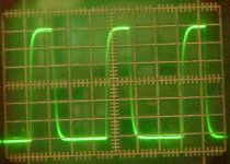
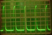
1) 32 kHz; 2) 60 kHz; 3) 100 kHz.
1) 32 kHz; 2) 60 kHz; 3) 100 kHz.
Attachments
Last edited:


Congratulationst, glad you like it 🙂
Seb, at a current of 120 mA, excellent sound is obtained. The radiators are cold.😉
Unbalanced 2 Balanced Line Driver
OPA1632 Fully-Differential Audio Operational Amplifier Board ADC Driver Module | eBay
OPA1632 Fully-Differential Audio Operational Amplifier Board ADC Driver Module | eBay
Micro-Cap 12 Sims
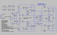
FYI, some new simulation results using Micro-Cap 12 (free download here). All results are with input stage driven unbalanced.
1. Test circuit using only Vas emitter resistors as compensation
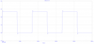
2. 10 kHz square wave response with 1 uF in parallel with 8 ohms
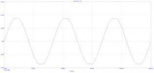
3. 10 kHz clipping waveform with 1.8 V peak unbalanced input
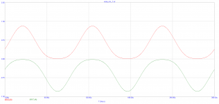
4. Class A currents with output stage devices biased @ 400 mA
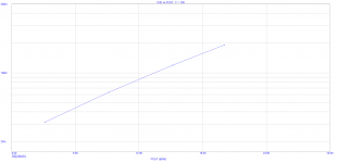
5. 10 kHz THD vs. output power (in peak dBW; 20 dBW = 50 W RMS)
In simulation, the only real difference I see when driving the input unbalanced is the presence of even harmonics (mostly H2) in the output distortion spectrum, which may or may not be audible.
I'm still new to Micro-Cap but it appears to be an excellent simulator with really good component libraries, including vacuum tubes. Interested to see how these results compare with the real circuit...
FYI, some new simulation results using Micro-Cap 12 (free download here). All results are with input stage driven unbalanced.
1. Test circuit using only Vas emitter resistors as compensation
2. 10 kHz square wave response with 1 uF in parallel with 8 ohms
3. 10 kHz clipping waveform with 1.8 V peak unbalanced input
4. Class A currents with output stage devices biased @ 400 mA
5. 10 kHz THD vs. output power (in peak dBW; 20 dBW = 50 W RMS)
In simulation, the only real difference I see when driving the input unbalanced is the presence of even harmonics (mostly H2) in the output distortion spectrum, which may or may not be audible.
I'm still new to Micro-Cap but it appears to be an excellent simulator with really good component libraries, including vacuum tubes. Interested to see how these results compare with the real circuit...
Attachments
Interested to see how these results compare with the real circuit...
I took apart my experimental PCB. It is necessary to restore back.
Maybe Yurik_V wants to try this option.😉
HI,
hello, thank you Joe it is true that it could be interesting to do without capacitive compensation.
i don't have too much time right now, but was planning to add an emitter follower for an update or upgrade
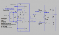
RAY_evolution.png is the most efficient, but the most difficult to tame, the 2nd is just a simulation that I tried thinking of a lunch break, there is no optimization
what do you think?
hello, thank you Joe it is true that it could be interesting to do without capacitive compensation.
i don't have too much time right now, but was planning to add an emitter follower for an update or upgrade
RAY_evolution.png is the most efficient, but the most difficult to tame, the 2nd is just a simulation that I tried thinking of a lunch break, there is no optimization
what do you think?
Attachments
Last edited:
Amplifiers without feedback sound better even with increased distortion.
Seb, think about how to loosen the connection - 1k. It is probably necessary to reduce the supply voltage at preliminary stages.
Seb, think about how to loosen the connection - 1k. It is probably necessary to reduce the supply voltage at preliminary stages.
With respect that's nonsense. Distortion, if too bad, is audible, feedback can reduce distortion and, very importantly for bass speakers, increase damping factor, with no downside. Amps with no global feedback can be low distortion, and perform well, but high damping factor is much harder to achieve, so bass driver control is compromized - modern ported speakers assume low driving impedance and are tuned under this assumption.Amplifiers without feedback sound better even with increased distortion.
Go do some double-blind testing before using phrases like "sound better" - the limits to human acoustic perception of distortion are pretty well understood, as is expectation bias. If you think intermodulation distortion sounds better, then that's personal taste, not accurate reproduction.

If you think intermodulation distortion sounds better, then that's personal taste, not accurate reproduction.
Tastes are different for everyone. Someone likes the monitor sound, and someone like a warm tube. A low distortion amplifier does not always sound better.
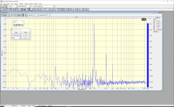
In the attachment, the spectrum of the amplifier is without feedback. Yes, this amplifier has increased output impedance. But if we make amplifiers on our own, why can't we make an acoustic system for our amplifier? 😉
Attachments
There is no sound source in the world to have feedback, and amplifiers should be like that.
And there are already circuits of such amplifiers.
And there are already circuits of such amplifiers.
There is no sound source in the world to have feedback, and amplifiers should be like that.
And there are already circuits of such amplifiers.
You're displaying a complete lack of logic or basic analytical thought. Sound sources make sound, they do not reproduce sound. An amplifier reproduces sound, it doesn't make its own sound, they are different things - so why should different things be like each other?. You should try thinking things through, not taking on doctrines without critical thought.
The idea that like requires like is superstition like the Doctrine of signatures - Wikipedia
The aim of an amplifier is to make the output (under load) resemble the input as closely as possible (other than being bigger of course). Any technique that increases the resemblance is worth considering, especially if its easy and cheap and reliable. Negative feedback is easy and cheap and reliable(*). Negative feedback is precisely engineered to drive the error of the output down as low as possible, and has the side effect of lowering output impedance and flattening frequency response. It takes a poor circuit and makes it acceptable, and a good circuit and makes it exceptional.
The downside is preventing instability but that's very much a known science, although more complicated than some aspects of circuit design.
Most circuits without global negative feedback use local feedback, its actually hard not to do this with transistors where stable biasing relies on DC feedback.
(*) given cheap active devices with lots of gain are available - if gain is expensive, feedback will increase costs markedly.
- Home
- Amplifiers
- Solid State
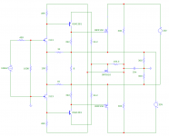
- Current feedback Mosfet Circlotron