Since the "standard" pentode symbol only has 4 pins, you will need to add another pin, then make sure the pin order of the new symbol matches that of the model.Can anyone modify it to work with standard Pentode symbol of LT Spice ?
6CY7 tube model
Section 1 Rydel model:
Section 1 Ayumi model:
Section 2 Koren model:
Section 2 Ayumi model:
Here you go... 😉I cannot find a spice model for 6CY7 tube, maybe someone here have it......all the best
Section 1 Rydel model:
Code:
* ==============================================================
* 6CY7_1 LTSpice model (section 1)
* Rydel model (5 parameters): mean fit error 0.0546128mA
* Traced by Wayne Clay on 02/19/2019 using Engauge Digitizer 10.4
* and Curve Captor v0.9.1 from General Electric data sheet
* ==============================================================
.subckt 6CY7_1  P G K
    Bp  P K  I=
+ ((0.001352184825m)+(1.505883023e-05m)*V(G,K))*uramp((65.68325206)*
+ V(G,K)+V(P,K)+(43.57867756))**1.5 * V(P,K)/(V(P,K)+(5.818213002))
    Cgp G P 2.5p ; 0.7p added (1.8p)
    Cgk G K 2.2p ; 0.7p added (1.5p)
    Cpk P K 0.5p ; 0.2p added (0.3p)
    Rpk P K 1G ; to avoid floating nodes
    d3  G K dx1
.model dx1 d(is=1n rs=2k cjo=1pf N=1.5 tt=1n)
.ends 6CY7_1
Code:
* ==============================================================
*
* Generic triode model: 6CY7_1_AN
* Copyright 2003--2008 by Ayumi Nakabayashi, All rights reserved.
* Version 3.10, Generated on Tue Feb 19 13:20:01 2019
*                 Plate
*                 | Grid
*                 | | Cathode
*                 | | |
.SUBCKT 6CY7_1_AN A G K
BGG   GG   0 V=V(G,K)+0.58239483
BM1   M1   0 V=(0.0018043738*(URAMP(V(A,K))+1e-10))**-0.18632668
BM2   M2   0 V=(0.88950736*(URAMP(V(GG)+URAMP(V(A,K))/61.236)+1e-10))**1.6863267
BP    P    0 V=0.00077179692*(URAMP(V(GG)+URAMP(V(A,K))/68.8426)+1e-10)**1.5
BIK   IK   0 V=U(V(GG))*V(P)+(1-U(V(GG)))*0.00052326937*V(M1)*V(M2)
BIG   IG   0 V=0.00038589846*URAMP(V(G,K))**1.5*(URAMP(V(G,K))/(URAMP(V(A,K))+URAMP(V(G,K)))*1.2+0.4)
BIAK  A    K I=URAMP(V(IK,IG)-URAMP(V(IK,IG)-(0.00040277594*URAMP(V(A,K))**1.5)))+1e-10*V(A,K)
BIGK  G    K I=V(IG)
* CAPS
CGA   G    A 1.8p
CGK   G    K 1.5p
CAK   A    K 0.3p
.ENDS
Code:
* ==============================================================
* 6CY7_2 LTSpice model (section 2)
* Modified Koren model (8 parameters): mean fit error 0.918378mA
* Traced by Wayne Clay on 02/19/2019 using Engauge Digitizer 10.4
* and Curve Captor v0.9.1 from General Electric data sheet
* ==============================================================
.subckt 6CY7_2  P G K
    Bp  P K  I=
+ (0.2452863892m)*uramp(V(P,K)*ln(1.0+(-0.1764710313)+exp((4.52352785)+
+ (4.52352785)*((7.111931873)+(2.926804722m)*V(G,K))*V(G,K)/sqrt((1.767549921e-05)**2+
+ (V(P,K)-(-22.14179645))**2)))/(4.52352785))**(1.417654512)
    Cgp G P 4.6p ; 0.2p added (4.4p)
    Cgk G K 5.7p ; 0.7p added (5.0p)
    Cpk P K 1.2p ; 0.2p added (1.0p)
    Rpk P K 1G ; to avoid floating nodes
    d3  G K dx1
.model (section 2) dx1 d(is=1n rs=2k cjo=1pf N=1.5 tt=1n)
.ends 6CY7_2
Code:
* ==============================================================
*
* Generic triode model: 6CY7_2_AN
* Copyright 2003--2008 by Ayumi Nakabayashi, All rights reserved.
* Version 3.10, Generated on Tue Feb 19 14:31:50 2019
*                 Plate
*                 | Grid
*                 | | Cathode
*                 | | |
.SUBCKT 6CY7_2_AN A G K
BGG   GG   0 V=V(G,K)+1
BM1   M1   0 V=(0.062983802*(URAMP(V(A,K))+1e-10))**-0.64998377
BM2   M2   0 V=(0.69767969*(URAMP(V(GG)+URAMP(V(A,K))/4.7999693)+1e-10))**2.1499838
BP    P    0 V=0.0028039793*(URAMP(V(GG)+URAMP(V(A,K))/6.8799041)+1e-10)**1.5
BIK   IK   0 V=U(V(GG))*V(P)+(1-U(V(GG)))*0.001628201*V(M1)*V(M2)
BIG   IG   0 V=0.0014019897*URAMP(V(G,K))**1.5*(URAMP(V(G,K))/(URAMP(V(A,K))+URAMP(V(G,K)))*1.2+0.4)
BIAK  A    K I=URAMP(V(IK,IG)-URAMP(V(IK,IG)-(0.0020350348*URAMP(V(A,K))**1.5)))+1e-10*V(A,K)
BIGK  G    K I=V(IG)
* CAPS
CGA   G    A 4.4p
CGK   G    K 5p
CAK   A    K 1p
.ENDS
Attachments
wowww thank you so much you are an angel.....all the bestHere you go... 😉
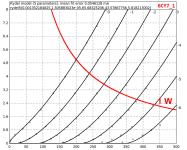
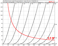
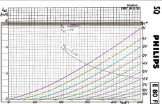
Here is my adjusted e80f_p model with the aid of g2 curve, the screen current is now better fitted than the previous model.
Code:
**** E80F_P ******************************************
* Created on 02/23/2019 22:59 using paint_kip.jar
* [URL="http://www.dmitrynizh.com/tubeparams_image.htm"]www.dmitrynizh.com/tubeparams_image.htm[/URL]
* Plate Curves image file: e80f_p.png
* Data source link: <plate curves URL>
*----------------------------------------------------------------------------------
.SUBCKT E80F_P P G2 G K ; LTSpice tetrode.asy pinout
* .SUBCKT E80F_P P G K G2 ; Koren Pentode Pspice pinout
+ PARAMS: MU=23.26 KG1=2830.31 KP=1281.54 KVB=0 VCT=0 EX=1.355 KG2=1932.42 KNEE=14.61 KVC=1.72
+ KLAM=1.562E-9 KLAMG=4.687E-7   KNK=-0.044 KNG=0.006 KNPL=50 KNSL=11 KNPR=120 KNSR=29
+ CCG=5P CGP=0.025P CCP=7.3P RGI=2000.0
* Vp_MAX=500 Ip_MAX=10 Vg_step=2 Vg_start=0 Vg_count=11
* X_MIN=63 Y_MIN=58 X_SIZE=768 Y_SIZE=765 FSZ_X=1550 FSZ_Y=878 XYGrid=false
* Rp=1400 Vg_ac=20 P_max=1.3 Vg_qui=-10 Vp_qui=300
* showLoadLine=n showIp=y isDHP=n isPP=n isAsymPP=n isUL=n showDissipLimit=y
* showIg1=n isInputSnapped=y addLocalNFB=n
* XYProjections=n harmonicPlot=y dissipPlot=n
* UL=0.43 EG2=108 gridLevel2=n addKink=y isTanhKnee=n advSigmoid=n
*----------------------------------------------------------------------------------
RE1  7 0  1G    ; DUMMY SO NODE 7 HAS 2 CONNECTIONS
E1   7 0  VALUE=  ; E1 BREAKS UP LONG EQUATION FOR G1.
+{V(G2,K)/KP*LOG(1+EXP((1/MU+(VCT+V(G,K))/SQRT(KVB+V(G2,K)*V(G2,K)))*KP))}
RE2  6 0  1G    ; DUMMY SO NODE 6 HAS 2 CONNECTIONS
E2  6 0  VALUE={(PWR(V(7),EX)+PWRS(V(7),EX))} ; Kg1 times KIT current
RE21 21 0 1
E21  21 0 VALUE={V(6)/KG1*ATAN(V(P,K)/KNEE)} ; Ip with knee but no slope and no kink
RE22 22 0 1 ; E22: kink curr deviation for plate
E22  22 0 VALUE={V(21)*LIMIT(KNK-V(G,K)*KNG,0,0.3)*(-ATAN((V(P,K)-KNPL)/KNSL)+ATAN((V(P,K)-KNPR)/KNSR))}
G1   P  K  VALUE={V(21)*(1+KLAMG*V(P,K))+KLAM*V(P,K) + V(22)}
* Alexander Gurskii screen current, see audioXpress 2/2011, with slope and kink added
RE43 43 K 1G ; Dummy
E43  43 G2 VALUE={0} ; Dummy
G2   43 K  VALUE={V(6)/KG2*(KVC-ATAN(V(P,K)/KNEE))/(1+KLAMG*V(P,K))-V(22)}
RCP  P K  1G     ; FOR CONVERGENCE
C1   K G  {CCG}  ; CATHODE-GRID 1
C2   G P  {CGP}  ; GRID 1-PLATE
C3   K P  {CCP}  ; CATHODE-PLATE
R1   G 5  {RGI}  ; FOR GRID CURRENT
D3   5 K  DX     ; FOR GRID CURRENT }
.MODEL DX D(IS=1N RS=1 CJO=10PF TT=1N)
.ENDS
*$


* The following triode model is derived from pentode model, see above.
* In the triode model, all spice parameters come directly from the pentode model, except for Kg1,
* which for triode-strapped pentodes is derived from pentode's Kg1, Kg2 and Kvc as
*
*    4Kg1Kg2 / ((2Kvc-Pi)(2Kg1+PiKg2))

**** E80F_P ******************************************
* Created on 02/23/2019 22:59 using paint_kit.jar 4.7
* [URL="http://www.dmitrynizh.com/tubeparams_image.htm"]www.dmitrynizh.com/tubeparams_image.htm[/URL]
* Plate Curves image file: e80f_p.png
* Data source link: <plate curves URL>
*----------------------------------------------------------------------------------
.SUBCKT TRIODE_E80F_P 1 2 3 ; Plate Grid Cathode
+ PARAMS: CCG=5P  CGP=0.025P CCP=7.3P RGI=2000
+ MU=23.26 KG1=6245.28 KP=1281.54 KVB=0 VCT=0 EX=1.355
* Vp_MAX=500 Ip_MAX=10 Vg_step=2 Vg_start=0 Vg_count=11
* Rp=1400 Vg_ac=20 P_max=1.3 Vg_qui=-10 Vp_qui=300
* X_MIN=63 Y_MIN=58 X_SIZE=768 Y_SIZE=765 FSZ_X=1550 FSZ_Y=878 XYGrid=false
* showLoadLine=n showIp=y isDHT=n isPP=n isAsymPP=n showDissipLimit=y
* showIg1=n gridLevel2=n isInputSnapped=y
* XYProjections=n harmonicPlot=y dissipPlot=n
*----------------------------------------------------------------------------------
E1 7 0 VALUE={V(1,3)/KP*LOG(1+EXP(KP*(1/MU+(VCT+V(2,3))/SQRT(KVB+V(1,3)*V(1,3)))))}
RE1 7 0 1G  ; TO AVOID FLOATING NODES
G1 1 3 VALUE={(PWR(V(7),EX)+PWRS(V(7),EX))/KG1}
RCP 1 3 1G   ; TO AVOID FLOATING NODES
C1 2 3 {CCG} ; CATHODE-GRID
C2 2 1 {CGP} ; GRID=PLATE
C3 1 3 {CCP} ; CATHODE-PLATE
D3 5 3 DX ; POSITIVE GRID CURRENT
R1 2 5 {RGI} ; POSITIVE GRID CURRENT
.MODEL DX D(IS=1N RS=1 CJO=10PF TT=1N)
.ENDS
*$
Attachments
12sx7GT model
Hello,
I'm looking for 12sx7gt tube, near from 12sn7gt but ...seem to be for lower Anode voltages
If someone have it.. ?
Thanks
Hello,
I'm looking for 12sx7gt tube, near from 12sn7gt but ...seem to be for lower Anode voltages
If someone have it.. ?
Thanks
12SX7 SPICE Model
Code:
*
* Generic triode model: 12SX7_AN
* Copyright 2003--2008 by Ayumi Nakabayashi, All rights reserved.
* Version 3.10, Generated on Tue Mar 05 15:55:02 2019
*                Anode
*                | Grid
*                | | Cathode
*                | | |
.SUBCKT 12SX7_AN A G K
BGG   GG   0 V=V(G,K)+0.72216423
BM1   M1   0 V=(0.013069022*(URAMP(V(A,K))+1e-10))**-0.44524966
BM2   M2   0 V=(0.77110924*(URAMP(V(GG)+URAMP(V(A,K))/17.513993)+1e-10))**1.9452497
BP    P    0 V=0.00093480926*(URAMP(V(GG)+URAMP(V(A,K))/22.712726)+1e-10)**1.5
BIK   IK   0 V=U(V(GG))*V(P)+(1-U(V(GG)))*0.00054432628*V(M1)*V(M2)
BIG   IG   0 V=0.00046740463*URAMP(V(G,K))**1.5*(URAMP(V(G,K))/(URAMP(V(A,K))+URAMP(V(G,K)))*1.2+0.4)
BIAK  A    K I=URAMP(V(IK,IG)-URAMP(V(IK,IG)-(0.00052981619*URAMP(V(A,K))**1.5)))+1e-10*V(A,K)
BIGK  G    K I=V(IG)
* CAPS
CGA   G    A 7p
CGK   G    K 7p
CAK   A    K 1.1p
.ENDS12SX7GT Koren model
I see jazbo8 beat me to it. Here's a 12SX7GT model I made using Curve Captor awhile back.
I see jazbo8 beat me to it. Here's a 12SX7GT model I made using Curve Captor awhile back.
Code:
* ==============================================================
* 12SX7GT LTSpice model
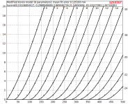
* Modified Koren model (6 parameters): mean fit error 0.125193mA
* Traced by Wayne Clay on 09/22/2018 using WebPlotDigitizer
* and Curve Captor v0.9.1 from Tung-Sol data sheet
* ==============================================================
.subckt 12SX7GT P G K
Bp P K I=
+ (0.03106854417m)*uramp(V(P,K)*ln(1.0+(-0.2988948689)+exp((3.869446728)+(3.869446728)*
+ ((21.54650694)+(-81.03227083m)*V(G,K))*V(G,K)/V(P,K)))/(3.869446728))**(1.26718281)
Cgp G P 4.1p ; 0.5p added (3.6p)
Cgk G K 3.2p ; 0.2p added (3.0p)
Cpk P K 1.7p ; 0.5p added (1.2p)
Rpk P K 1G ; to avoid floating nodes
d3 G K dx1
.model dx1 d(is=1n rs=2k cjo=1pf N=1.5 tt=1n)
.ends 12SX7GTAttachments
Results about 12SX7 models
Hello !
Thanks for your help ! sorry for my approximative vocabulary
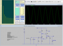
I'm a beginner, I'm trying to build a low voltage line preamp, the original schematic is from JR Broskie (Tubecad),
Pictures attached :
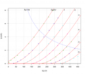
Jazbo model green curves : R on plate : 600 ohms
Cogsncogs model yellow curves : R on plate : 700 ohms
the results are very near with this only small modification
I'm happy with results !
Richard
Hello !
Thanks for your help ! sorry for my approximative vocabulary
I'm a beginner, I'm trying to build a low voltage line preamp, the original schematic is from JR Broskie (Tubecad),
Pictures attached :
Jazbo model green curves : R on plate : 600 ohms
Cogsncogs model yellow curves : R on plate : 700 ohms
the results are very near with this only small modification
I'm happy with results !
Richard
Attachments
Hi,
just want to inform you that I fitted a RCA 6H6 twin diode. This vacuum diode is mainly intended for use in AGC circuits to determine the small signal amplitude level, or for audion detector circuits.
Both applications needs good spice models considering the diodes "Anlauf" current.
As always, you will find the spice code and also diagrams showing the achieved fit quality on my website:
http://adrianimmler.simplesite.com/440956786
all the best, Adrian
12SX7GT RCA Koren model
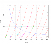
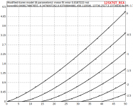
Here is a model I traced in Curve Captor from the curves in the RCA data sheet.Jazbo model green curves : R on plate : 600 ohms
Cogsncogs model yellow curves : R on plate : 700 ohms
the results are very near with this only small modification
I'm happy with results !
Richard
Code:
* ==============================================================
* 12SX7GT_RCA LTSpice model
* Modified Koren model (8 parameters): mean fit error 0.0187222mA
* Traced by Wayne Clay on 03/06/2019 using WebPlotDigitizer
* and Curve Captor v0.9.1 from RCA data sheet
* ==============================================================
.subckt 12SX7GT_RCA  P G K
    Bp  P K  I=
+ (0.0008174867855m)*uramp(V(P,K)*ln(1.0+(-0.3479097262)+exp((0.03708844881)+
+ (0.03708844881)*((456.118506)+(-13736.2517m)*V(G,K))*V(G,K)/sqrt((3.137381814e-06)**2+
+ (V(P,K)-(-1.739695943))**2)))/(0.03708844881))**(1.304873602)
    Cgp G P 4.1p ; 0.5p added (3.6p)
    Cgk G K 3.2p ; 0.2p added (3.0p)
    Cpk P K 1.7p ; 0.5p added (1.2p)
    Rpk P K 1G ; to avoid floating nodes
    d3  G K dx1
.model dx1 d(is=1n rs=2k cjo=1pf N=1.5 tt=1n)
.ends 12SX7GT_RCA
Attachments
Hi Artemka
Spice models for Triodes intended for operation with grid current is my specialty!😀😀
Unfortunately, I have no time today - I will deliver it tomorrow, ok?
all the best, Adrian
Spice models for Triodes intended for operation with grid current is my specialty!😀😀
Unfortunately, I have no time today - I will deliver it tomorrow, ok?
all the best, Adrian
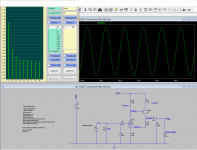
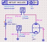
Hey Adrian! Thanks for the fast response! I have found a model of similar tube from Svetlana (SV811-10) at duncanamps.com, however I get some strange results (please see the picture below): the anode current is extremely high even if grid is grounded.Hi Artemka
Spice models for Triodes intended for operation with grid current is my specialty!😀😀
BR Artem
Attachments
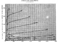
Hello.
Real characteristics downloaded from 6J7MG Sylvania tube in triode only up to 300V, but I have such a power supply.
Piotr
* 6J7MGM LTSpice model
.subckt 6J7MG P G K
Bp P K I=(0.01473731961m)*uramp(V(P,K)*ln(1.0+(-0.03756065666)+exp((5.686963717)+(5.686963717)*((23.96161429)+(43.74289348m)*V(G,K))*V(G,K)/sqrt((2.498892749e-006)**2+(V(P,K)-(-11.83444185))**2)))/(5.686963717))**(1.365051609)
Cgp G P 2.5p ; 0.25p added (2.25p)
Cgk G K 6.0p ; 0.5p added (5.5p)
Cpk P K 11.4p ; 1.4p added (10.p)
Rpk P K 1G ; to avoid floating nodes
d3 G K dx1
.model dx1 d(is=1n rs=2k cjo=1pf N=1.5 tt=1n)
.ends 6J7MG
Attachments
How do you know that the SV811 is equivalent to the 811A?Based on the attached curves for that tube it is too much.
[Edit] Please see: SE SV-811-10 power supply
- Home
- Amplifiers
- Tubes / Valves
- Vacuum Tube SPICE Models