680ohm 🙂
That's also the value supplied in the kits I made.
That's a good answer! Because that is what I soldered in.
To all who have the kit of parts that I made -
I supplied the wrong capacitor for the lead/lag network (C4). In the kit is 330pF where the schematic and PCB are both labeled 220pF. (Thanks to Gary S for bringing that to my attention 🙂 )
The good news is Wayne has tried and tested this value in the circuit and has declared it fine. No measurable difference in the audio band, and the only changes were minor and up near 5MHz.
Sorry about the error, but it looks like the audio gods are smiling on this project.
Carry on and build amps.
(Preamps, more specifically...)
Thanks for the follow up with Wayne on cap C4 - I will use the supplied Wima 330pF, no problems. My ears don't go any where near 5MHz nor do the speakers, so all is fine.
To all who have the kit of parts that I made -
I supplied the wrong capacitor for the lead/lag network (C4). In the kit is 330pF where the schematic and PCB are both labeled 220pF. (Thanks to Gary S for bringing that to my attention 🙂 )
The good news is Wayne has tried and tested this value in the circuit and has declared it fine. No measurable difference in the audio band, and the only changes were minor and up near 5MHz.
Sorry about the error, but it looks like the audio gods are smiling on this project.
Carry on and build amps.
(Preamps, more specifically...)
Insignificant difference, I measured around 330pf with my meter and installed them anyways in 220pf spot without giving a second thought. We are dealing with pf.
Really stupid question, but there seems to be one version of the schematic with R23/C4 and one without - what's the difference?
Big output transistors.
KSA1220A / KSC2690A
The Lead/Lag network is removed, the output emitter resistors are 1/2w and different value, and the feedback cap if 5pF
KSA1220A / KSC2690A
The Lead/Lag network is removed, the output emitter resistors are 1/2w and different value, and the feedback cap if 5pF
I have my headphones on listening to it this very moment I'm typing. (The point of the big outputs being they have enough power to directly drive headphones.) ((And whatever insane cable runs you could possibly envision))
Sounds wonderful!! Photos soon.
Sounds wonderful!! Photos soon.
headphones are for Sissies

(ZM making a pair of Wayne's can amps , one for Nephew , one for my self ...... blasphemy - ZM using OP amps ..... though , partially lesser blame , there are some LEDs shining in there 🙂 )
(ZM making a pair of Wayne's can amps , one for Nephew , one for my self ...... blasphemy - ZM using OP amps ..... though , partially lesser blame , there are some LEDs shining in there 🙂 )
This isn't a substitute for the Whammy, but it's neat to have the ability if you want it!
An externally hosted image should be here but it was not working when we last tested it.
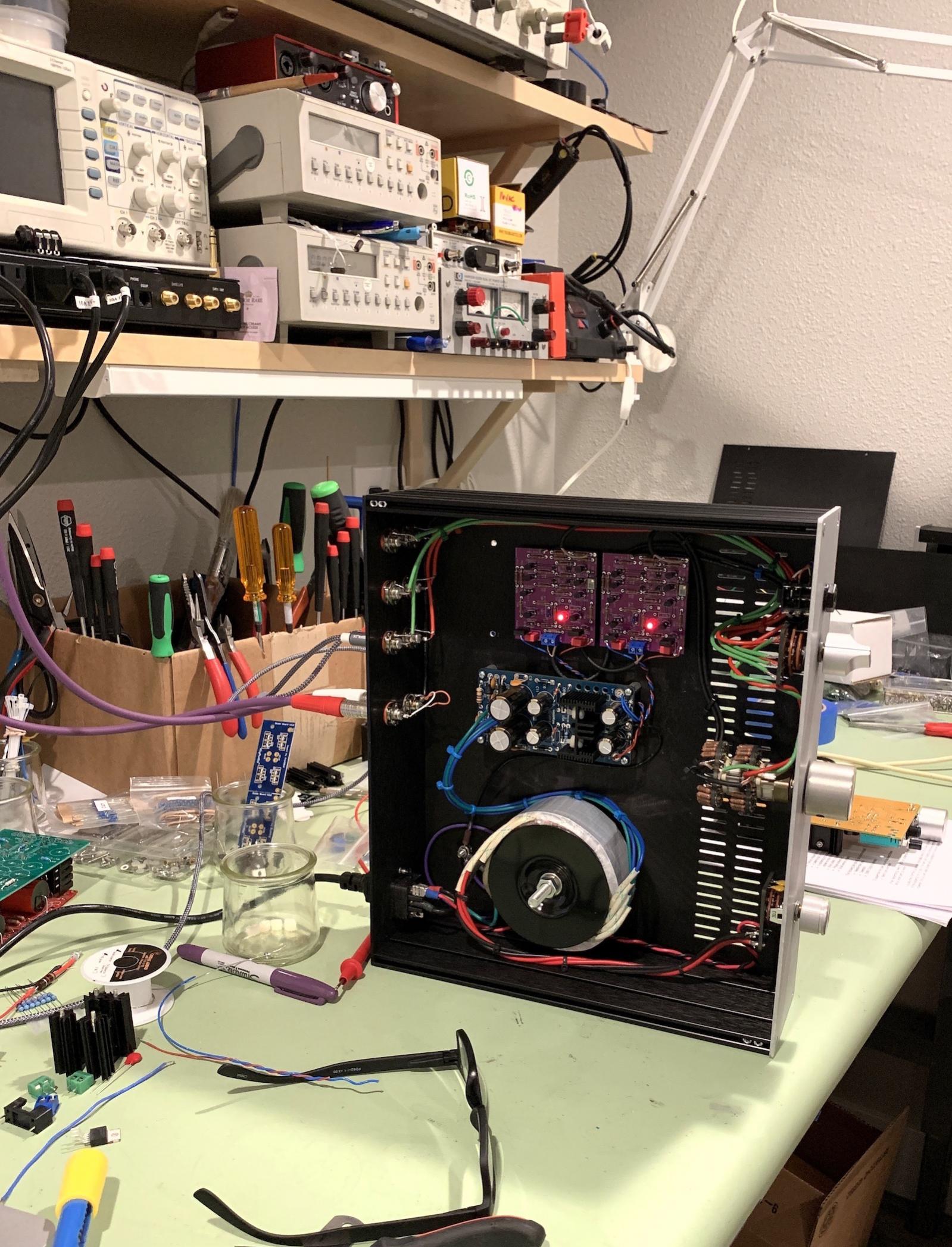
So I took the chassis with the BA-3 Preamp and removed the gain stage and replaced it with the purple boards.
These have the alternate outputs, in the TO-126 package, and have plenty of drive for my low-impedance headphones. PSU voltage is high enough to drive high-impedance phones as well.
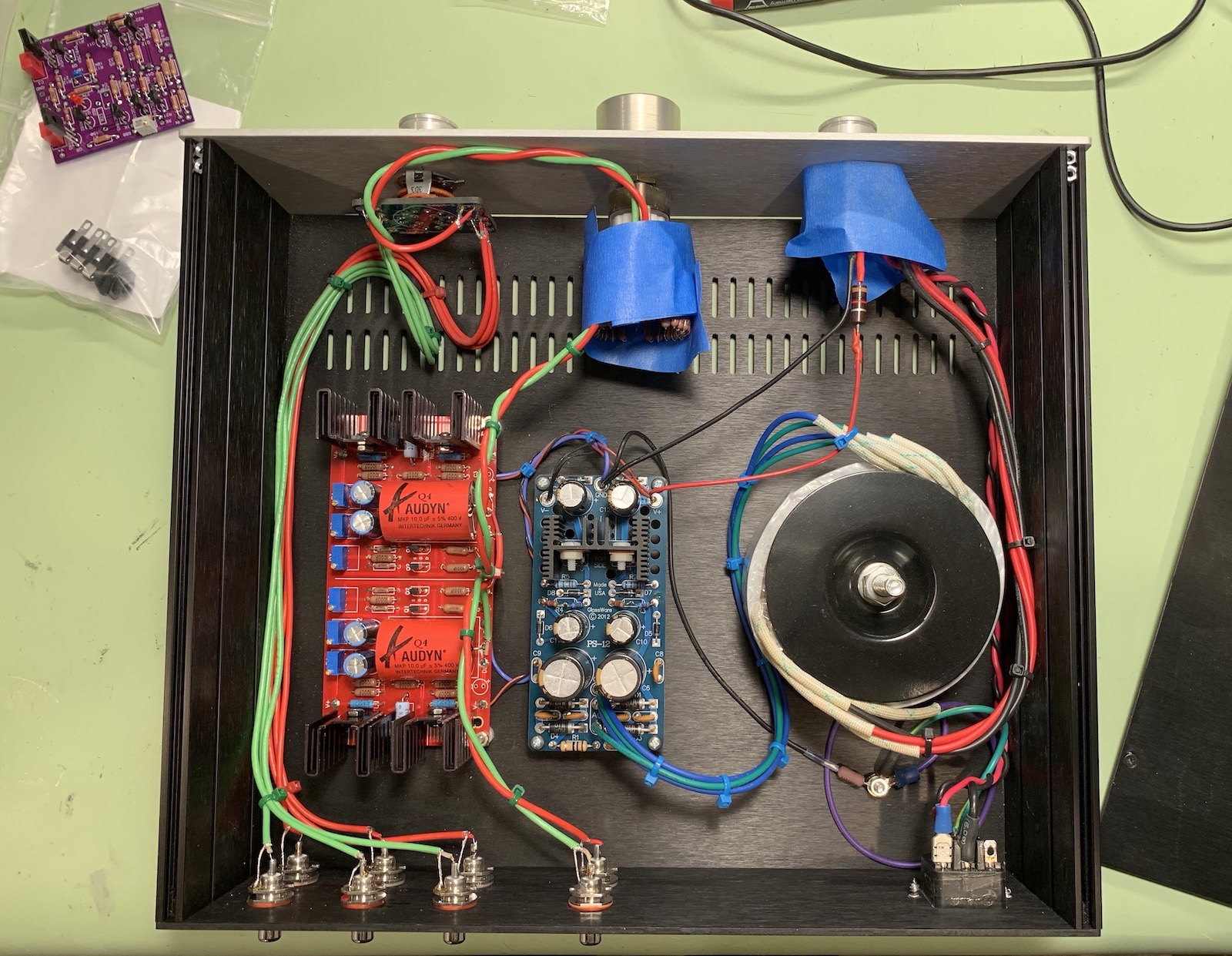
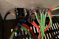
The BA-3 preamp. Taping the switches and attenuator up as work is done on it. Yes, the transformer is enormous, it was intended for a chipamp project that never happened. It's super quiet and was the right voltage. And was on my my shelf... 🙂
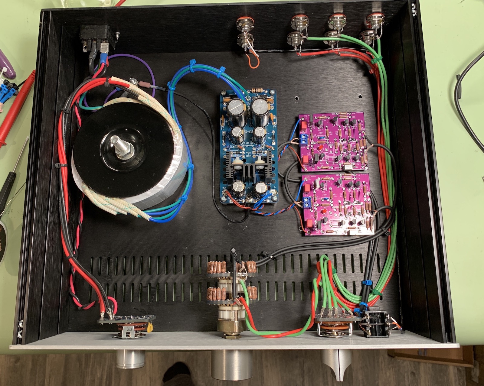
Installed with the purple boards.
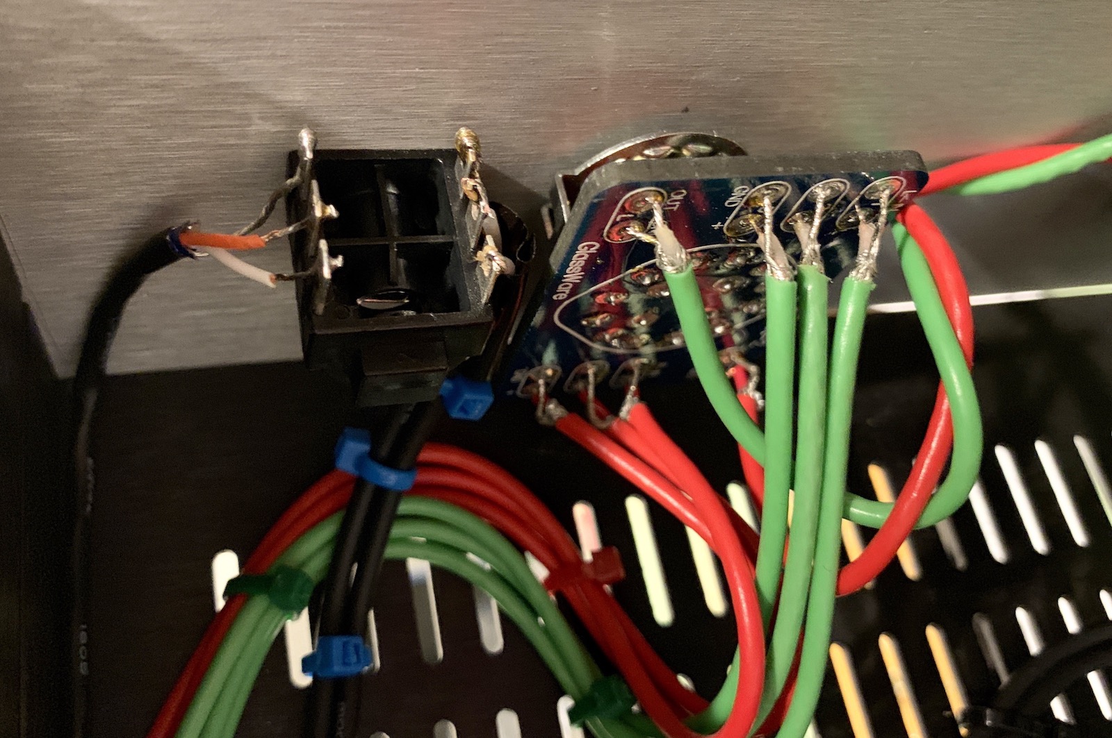
The headphone jack is a switched type, it will pass through the signal if no plug is installed, and send the signal to headphones if installed. So the jack is wired first on the output of the boards, and then output RCAs are further downstream.
I'm going to install the Broskie regulator (and a more reasonable transformer 🙂 ) next and take more photos of the connections.
These have the alternate outputs, in the TO-126 package, and have plenty of drive for my low-impedance headphones. PSU voltage is high enough to drive high-impedance phones as well.
The BA-3 preamp. Taping the switches and attenuator up as work is done on it. Yes, the transformer is enormous, it was intended for a chipamp project that never happened. It's super quiet and was the right voltage. And was on my my shelf... 🙂
Installed with the purple boards.
The headphone jack is a switched type, it will pass through the signal if no plug is installed, and send the signal to headphones if installed. So the jack is wired first on the output of the boards, and then output RCAs are further downstream.
I'm going to install the Broskie regulator (and a more reasonable transformer 🙂 ) next and take more photos of the connections.
Attachments


Last edited:
- Home
- Amplifiers
- Pass Labs
- Wayne's BA 2018 linestage