Excuse me, but that simply isn't true. Just because something sounds interesting doesn't make it factual. The analysis being given simply does not hold up to scientific rigor. It's all a smoke screen for something that has always been there, has always been understood and simpy is not a mystery. For example: calling an inductive impedance a "back EMF" is simply symantec. Would we call a capacitors impedance a "forward EMF".
SMH, everything in audio does NOT have to be proven by scientific rigor. There are somethings that cant be quantified as such hence my statement and why I say you shouldn't proclaim something as a "nothing". People love ZU Audio despite their horrid measurement or brochure literature. No scientific rigor will explain that one. Just cause an idea isn't up to your scientific rigor, shouldn't stop anyone from exploring. If you want to argue the verbiage (emf) people use and how they're using it, have it at still the exploration shouldn't be avoided.
A logical explanation only works if those listening take it seriously. If you ridicule a subject, you will never understand it. That is just how things are. But it is being taken seriously by some serious people, even if they are not here. This is not some thought bubble by somebody who has isolated himself and not taken challenges seriously and then having to find a way to either explain or discard. Both leads to advancement, and that is the most important.
Is this off topic? Will it ever be on topic? I wonder. But hijacking, well, I would respect what ever Lynne says and be guided by that. Is that not fair?
Is this off topic? Will it ever be on topic? I wonder. But hijacking, well, I would respect what ever Lynne says and be guided by that. Is that not fair?
Start a new thread yo, i'd most definitely subscribe and keep up w it. If it falls to the wayside it'll be in the search archive at least
Now hold on a moment... "beyond the Ariel" OP Olson was moving to unboxed dipoles. That's a "suspension" that perks the interest in current-drive because the sound output, at least in the bass, is more purely related to the VC. Major problem that amps and speakers have mostly come out of different boxes - dumb, eh.f'There cannot be found any scientifically valid reasons that justify the adoption of voltage...
I think if you think about the commercialization and marketing of audio amps, voltage-feedback amps are a whole lot simpler universe than current-feedback. And other reasons for manufacturers to go in that direction, then and now. With motional feedback thrown in, ten times harder to commercialize.
And as I've said too many times, with drivers now artfully crafted to play right with constant-voltage drive, nobody is budging.
But for DIY and experimental crowd here, commercial imperatives don't matter much.
B.
Last edited:
I think if you think about the commercialization and marketing of audio amps, voltage-feedback amps are a whole lot simpler universe than current-feedback.
Please don't add the voltage vs current feedback amplifier controversy to this. Voltage out vs current out amplifiers is the issue. My complaints about this side thread are technical points that are simply wrong, Kirchhoff's laws are not a matter of opinion.
Last edited:
I have read very extensively and every time I have more confusion ....
It will be that I do not remember the basic electronics well?
First, in a basic circuit of alternating current, the current that will circulate will be the result of the division of the voltage on the load. ( resistance )
Okay ?
Well, now we replace the resistor (fixed load) with a variable load (the voice coil interacting with the magnetic field of the speaker motor) and the dance starts.
We have (as far as I can remember) an inductive type reactance. I do not see capacitive reactances, am I wrong? Because so much emphasis in the current vs. the voltage as if one did not absolutely depend on the other?
Is not all this absolutely studied by traditional electronics?
What has changed so much to arrive at this series of reasonings so confusing for me ...? .
I agree with all your questions, but you have one error. There is a virtual capacitor in this circuit. It comes from the back EMF above resonance. Below resonance the phase difference between the voltage and current makes the impedance look inductive, then at resonance it is a purely real resistance, but above resonance it looks just like a capacitor and as far as the amp is concerned it is a capacitor. At HFs we have a pure inductance from the voice-coil.
All this results from the back EMF and how it negates some of the amps voltage thus decreasing the amps current. This then looks exactly like an impedance, where the type of component depends on the phase of the EMF, which depends on the mechanics of the system.
That's how things really work.
All this results from the back EMF and how it negates some of the amps voltage thus decreasing the amps current. This then looks exactly like an impedance, where the type of component depends on the phase of the EMF, which depends on the mechanics of the system.
That's how things really work.
ANd then there is the fact that voltage amps work just fine!
That is if there is no desire to make things better.
I have read very extensively and every time I have more confusion ....
It will be that I do not remember the basic electronics well?
First, in a basic circuit of alternating current, the current that will circulate will be the result of the division of the voltage on the load. ( resistance )
Okay ?
Well, now we replace the resistor (fixed load) with a variable load (the voice coil interacting with the magnetic field of the speaker motor) and the dance starts.
We have (as far as I can remember) an inductive type reactance. I do not see capacitive reactances, am I wrong? Because so much emphasis in the current vs. the voltage as if one did not absolutely depend on the other?
Is not all this absolutely studied by traditional electronics?
What has changed so much to arrive at this series of reasonings so confusing for me ...? .
First of all, look at the current phase vs voltage phase. Then look at how the moving weight acceleration phase. These add up.
Joe’s speaker does reduce Back EMF feeding it to the ground through the parallel network with the speaker load. There are two ways of doing this, flatten impedance at each driver individually, or flatten at the crossover where the amp sees the load. The latter requires less components. This does not solve the current phase issue through the voice coil. But improvement is audible.
Indeed they are audible and this will be with voltage source amps.
But please note the current EQ takes place where the amplifier sees it directly, the crossover filtering comes afterwards, so the main and first target is to get the voltage and current of amplifier in sync, in time. I am not in favour of altering the termination impedance of the driver. You want the impedance to go up due to external inductor and capacitor. They add predictable reactance/impedance between the amplifier and this is good. They also make EQ of the current of the amplifier easier to achieve. But you are right, it does not change the current phase through the voice coil, very perceptive of you. But it makes it less 'reactive' because the other series impedances are not unpredictable. They are easy to EQ. Hope that helps, but I can see you are making an effort to understand.
In other words, get the current phase angle of the amplifier to zero. Now you have prevented the amplifier from producing so-called reactive current.
I am not alone in this. I am sorry, but Earl's statement is simply not correct.
And I have an example that proves this is not the case, so please read this:
The huge majority of people are listening to Class AB amplifiers and in the transition between A and B, if the voltage and current being are not together, large (and measurable) bursts of higher order harmonics are generated when the 'voltage' correcting feedback has to be used to deal with it.
This has been measured by a Dutch scientist - Hans van Maanen of Temporal Coherence. I quote and please see attachment, his block diagram of a Class AB amplifier is very revealing. Here are the words associated with it.
"When the current through the load is not zero because of a phase shift between the two, one of the output transistors needs to deliver this current. But this is not possible unless an error voltage at the output can open one of the output transistors via the feedback loop! So distortion is introduced and this phenomenon tends to enhance cross-over distortion which is well-known for its highly annoying properties because it has the wide spectral distribution of harmonics as shown... A class-A amplifier is far less sensitive to this phenomenon (simply because there is always current flowing through the power transistors)..."
Not as an endorsement, Class D amplifiers are also less of a problem because they are PWM. But equalising current works with Class D amplifiers as well. So there are more than one mechanism at work. People are hearing an improvement, it sounds more sweet, more musical, more accessible to the ear. And you can do this in more ways than one. Not just current drive.
I have been in contact with several loudspeaker designers on this, the growing understanding of flattening the current phase angle is becoming more common.
There is a movement going on, and it is also gone beyond the usual battle of voltage versus current drive, it is now starting to be shifted more to let us start seriously thinking about what the current is doing and what current ends up flowing through the voice coil, because THAT is what you end up listening to.
Nothing new here, just a different focus - and I am at loss why Kirchoff's Law again seems to be invoked, it has nothing to do with it, period!

I am not trying to hijack anything, but things are happening on this front. Can't just wish it away. I would like to hear from Lynn, it is his thread.
I am in Aarhus right now, the centre of the Danish loudspeaker industry. The dynamic loudspeaker was a Danish invention by Peter Laurits Jensen in 1915.
And guess what we are talking about? Then at ETF18 in Normandy France next week, guess what we will be talking about? More people are focusing on the current side of things. But the voltage model is powerful - just not the full story.
Back home in Sydney in two weeks. And enjoying summer. 🙂
Cheers, Joe
Attachments
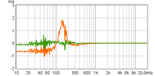
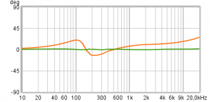
...get the voltage and current of amplifier in sync, in time...
Don't know why but REW verse other software has a feature to show group delay for measured impendances, so when you talk about sync in time any chance that REW feature or that curve in reverse figure can be related.
Below example show 25 times Vifa TC9 drivers in a line array, raw verse resonance/inductance compensated.
Attachments

Last edited:
Joe, you must have seen quite some opposition to this. You don't seem to notice the ways that I agree with you. It's just that there seem to be conclusions being drawn in unexpected places.
.and it can be seen as this. This had to be said.
You have some things to say about amplifiers which I find interesting.
This then looks exactly like an impedance,
.and it can be seen as this. This had to be said.
You have some things to say about amplifiers which I find interesting.
That is if there is no desire to make things better.
If an amp is inaudible, as it has been shown that many good designs are, then what is to be improved? Make them more audible as some amp designs do?
the amp may be inaudible and well behaved until it encounters a highly reactive load but then it becomes a chicken/egg thing, if the relationship between speaker and amp can be made better why not?
I agree with all your questions, but you have one error. There is a virtual capacitor in this circuit. It comes from the back EMF above resonance. Below resonance the phase difference between the voltage and current makes the impedance look inductive, then at resonance it is a purely real resistance, but above resonance it looks just like a capacitor and as far as the amp is concerned it is a capacitor. At HFs we have a pure inductance from the voice-coil.
All this results from the back EMF and how it negates some of the amps voltage thus decreasing the amps current. This then looks exactly like an impedance, where the type of component depends on the phase of the EMF, which depends on the mechanics of the system.
That's how things really work.
Well, I suppose that my limitations with the English language added to the often confusing / deficient transcriptions into Google's Spanish (to whom I am very grateful, but it would be impossible for me to participate here) make me unable to fully understand the concept " there is a virtual capacitive reactance in the speaker ".
I will try to deepen the subject, thank you for your response.
This reminds me of the good old days, even with their disappointments.
(I remember my disappointment when I connected my pirmer amplifier to DIY valves and had hums and oscillations, I delved into the subject (there was no internet, ja) and someone told me:
"It is all well connected, but the arrangement of the components in a completely random and according to your personal taste, (and not the basic rules of wiring, parallel cables and with angles in 90 degrees to avoid feedback loops by parasitic capacitances, etc, etc) are the ones that cause all these problems, you must do everything again "
I did it and it worked perfectly.
So I guess I'm in a similar situation, one or many things are slipping away ......😱
Thank you very much for your kind response.
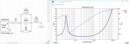
...make me unable to fully understand the concept " there is a virtual capacitive reactance in the speaker ".
This might help in understanding where the capacitor comes into picture. To model a simplified impedance of a loudspeaker unit, a few parts suffice to do that.
Attachments
While I agree this topic should be in it's own thread, I think its disingenuous proclaiming this is as "nothing" just cause others (or you) haven't looked into this thoroughly or feel its not worth the time. There's too many unknowns in this field the I would think everyone would encourage exploration. You may be right but there's too many angles for you or anyone else to thoroughly try, research and test all of them. I may be in the minority but I rather like reading different angles no matter how left field it may be
wow. the point was made regarding improvement in sound. arguing something like this is about like arguing for the old 8-track medium. it worked. the cartridges jammed a lot. but hey, SD, mp3 files, etc. are 'better' than 8-track. but there are those that can't hear HF & ambience, so the 8-track is fine with them.
for the 'old farts' in the group - tastes great. less filling.
A logical explanation only works if those listening take it seriously. If you ridicule a subject, you will never understand it. That is just how things are. But it is being taken seriously by some serious people, even if they are not here. This is not some thought bubble by somebody who has isolated himself and not taken challenges seriously and then having to find a way to either explain or discard. Both leads to advancement, and that is the most important.
Is this off topic? Will it ever be on topic? I wonder. But hijacking, well, I would respect what ever Lynne says and be guided by that. Is that not fair?
this seems to be the 'cold fusion' for audio. it is crap. most everybody in this thread knows it is crap. no one has said it is crap until now.
i tried to be polite with the elephant in the room, er blog: OCD. obsessive compulsive behavior disorder. when you simply can't let something go. even if it is minutiae, unimportant, insignificant, or crap.
this is crap and it deserves a separate crap thread.🙂
the amp may be inaudible and well behaved until it encounters a highly reactive load but then it becomes a chicken/egg thing, if the relationship between speaker and amp can be made better why not?
This is really the only point of any significance in all of this pointless discussion.
If the amp is designed such that it can handle the load presented by the speaker then it is "inaudible" and does not need to "be made better". If it can't then it isn't what I defined as a "good design"! So fix it! Don't waste time rambling on about things that have long since been solved and are no longer an issue.
- Status
- Not open for further replies.
- Home
- Amplifiers
- Solid State
- Back-EMF and flat impedance