Guess what, I just remembered I had a virgin MacBook Pro I can install IDE on, and that's what I just did.
Installed latest IDE, copied libraries.zip, restarted IDE, pulled one of the firmwares from link below, and it compiled right off the bat (with very few warnings due to new version of syntax which can be ignored).
I did not test if the new IDE make IR work, so make sure you use IDE 1.6.9 that works for sure.
Is it possible to run one wire for ground for R+ and A+ from psu to LDR board?
They seem shared on the psu pcb.
I have psu in separate enclosure and trying to make use of some connectors I have lying around, and I’m short one pin.
They seem shared on the psu pcb.
I have psu in separate enclosure and trying to make use of some connectors I have lying around, and I’m short one pin.
Yes.Is it possible to run one wire for ground for R+ and A+ from psu to LDR board?
They seem shared on the psu pcb.
I have psu in separate enclosure and trying to make use of some connectors I have lying around, and I’m short one pin.
This is the link to OLED I used:
I2C 2.42 128x64 Graphic OLED White Module ( Arduino / PIC / Multi-wii) with Hole | eBay
Hello, I'm very interested by use the 2.42 inch graphic Oled but at this page
I2C 2.42 128x64 Graphic OLED White Module ( Arduino / PIC / Multi-wii) with Hole | eBay
there is no more. I've found this one with SSD 1309
I2C 2.42 128x64 Graphic OLED White SSD1309( Arduino / PIC / Multi-wii) with Hole | eBay ,is it compatible with your code ?
Thanks a lot for you contribution at this project. SC
Go to WIDE.HK Technology, they should have one with ssd1306, i2c and 128x64. Ssd1309 is different controller.
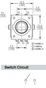
Encoder Connections.
Thank you Neb for taking the time to make and post the YouTube video. I found it very informative.
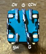
I don't understand how to connect the encoder to the board. I see 4 pads on the board-CW, CCW, SW and GND.
Looking at encoder's datasheet I see 5 terminals on it, none of which coincide with the board's connections of Clockwise, Counterclockwise, Switch and Ground as shown below.
I'm assuming the 2 connectors on top of the encoder are for the switch like shown in the datasheet.
Do I connect those to the SW and GND pads on the board?
How do I connect the encoder's Channel A and Channel B terminals to the CW and CCW pads on the board?
Thank you Neb for taking the time to make and post the YouTube video. I found it very informative.
I don't understand how to connect the encoder to the board. I see 4 pads on the board-CW, CCW, SW and GND.
Looking at encoder's datasheet I see 5 terminals on it, none of which coincide with the board's connections of Clockwise, Counterclockwise, Switch and Ground as shown below.
I'm assuming the 2 connectors on top of the encoder are for the switch like shown in the datasheet.
Do I connect those to the SW and GND pads on the board?
How do I connect the encoder's Channel A and Channel B terminals to the CW and CCW pads on the board?
Attachments
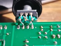
Have a look:
20180827_210402-klein.jpg (173.2 KB)
20180827_210428-klein.jpg (252.8 KB)
That works here.
Thanks for the photos Klaus, but I have the newer blue board not the older green one.
It's difficult for me to see the labeling of the pads on your board other than GND.


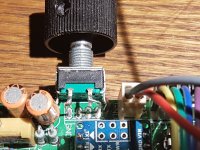
Thank you for the detailed photos Neb.
After looking closely at your photos in posts 1056 and 1057, it appears that CW and CCW are reversed in the photo in post 1057.
Nonetheless I get the idea as you suggested above thanks to your and Klaus's photos.
After looking closely at your photos in posts 1056 and 1057, it appears that CW and CCW are reversed in the photo in post 1057.
Nonetheless I get the idea as you suggested above thanks to your and Klaus's photos.
I have a same batch of encoders with some of them having reversed CW and CCW. Just try and reverse if direction is wrong.
A friend of mine compared Vxd preamp to Tortuga passive preamp:
LDR3.V25 Passive Preamp | Tortuga Audio
He says Tortuga is complete waste of money compared to gem in this thread😉
LDR3.V25 Passive Preamp | Tortuga Audio
He says Tortuga is complete waste of money compared to gem in this thread😉
- Home
- Source & Line
- Analog Line Level
- Arduino based LDR volume and source selection controller