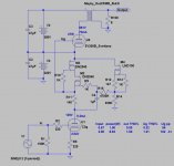
This is just a simulation in LTspice, quite reliable from euro21.
For some DIYers THD in simulation does not mean anything. But for me a good simulation gives good and valuable information.
In this case we have 5.1% THD @ 1.5Wrms output power and 1.68% Ug THD.
That's a lot really!
D3a is an extraordinary tube. But this big THD (especially Ug THD) indicates that the topology of this amplifier is not good and I would look for another tube for the driver stage.
Just IMO
In this case we have 5.1% THD @ 1.5Wrms output power and 1.68% Ug THD.
That's a lot really!
Remember that this is an SE amp with no feedback, at max power. I wouldn't be too concerned.
How much power do you need?
How much gain do you need?
No clue about which plate load choke to get. The Magnequest is $$$
What about an Electraprint AC6031?
IMHO, the amp's schematic is good
Sample schematic attached.
The longer I look at this, the more I feel like I want to make a headphone amp following this approach. This would require an OPT with a different winding ratio. I am thinking of low-impedance headphones (32 Ohm or so), but wouldn't mind some flexibility.
Does anyone know of an off-the-shelf parafeed tranny that would work well for this?
Are there any OPTs that have different taps or could be wired for different winding ratios (for example 32 ohm / 150 Ohm / 600 Ohm)?
This is a very, VERY common misconception. You'll actually get vastly better performance from a 4 ohm winding. If you get an OPT with an 8 ohm winding tapped at 4 ohms, you can use either for headphones. The dual 4 ohm windings with taps approach will give you the best of all worlds, but requires a rotary switch to get the different arrangements.The longer I look at this, the more I feel like I want to make a headphone amp following this approach. This would require an OPT with a different winding ratio. I am thinking of low-impedance headphones (32 Ohm or so), but wouldn't mind some flexibility.
You'll certainly want to plan on having a DC supply for the filaments.
You are going to find very few headphones (like 1 or 2) that need 2W at 32 ohms.
So what?
With SE amplifier w/o feedback (DC or not) it is very easy to get about 2-2.5% THD at full output power. It is classic.
Even 1% for 9Wrms output power.
Be careful. THD estimations by any spice software are simply not to be trusted.
For some DIYers THD in simulation does not mean anything. But for me a good simulation gives good and valuable information.
In good simulation...5,1% THD at max output power ..... that amp not be good. IMO.
Last edited:
Let me re-phrase post #47.
If you understand a little on how spice software is calculating distortion, you might not trust it at all anymore. 5% might be nonsense. 1% might be nonsense. etc.
If you understand a little on how spice software is calculating distortion, you might not trust it at all anymore. 5% might be nonsense. 1% might be nonsense. etc.
Hi RajkoM
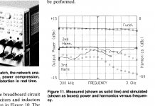
Simulations are ok for many things, but nothing can replace a measurement. I can't say much for the black and white image you post, since it is not in context and says nothing. We can only assume it was test bed for a simple small signal transistor circuit. No offence intended though.
If you investigate much spice software source code, what you often get is Fast Fourier Transform (FFT) implemented for universal small signal methods (only), in many instances with as little as 8 bit limitation (somewhere in the code), questionable bin dimensions, using the very best imperfect models we do our best to create...
For simulation of THD, I would be much more satisfied with a full monte carlo simulation using a circuit with perfect models. Maybe you have this? Very nice if you do.
I have a box of china 2a3's and the difference in measured THD for them at 1W output (single ended, no NFB, etc) varies from about 1% to 4%.
Last edited:
Why?I'm unfamiliar with the D3A.
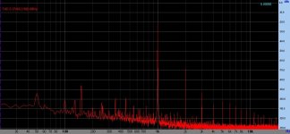
It's one of the most linear high gm driver tubes.
Sample: 70V RMS (198Vpp) "live" spectrum.
Attachments
No clue about which plate load choke to get.
See #22 post.
A gyrator is nice because it is smaller, cheaper, insensitive to hum/noise pickup, and is electronically closer to an "ideal inductor" than most real-world chokes. However, a gyrator requires a substantially higher B+ than a choke to accommodate for the voltage swing at the 45 plate.
Last edited:
This is a very, VERY common misconception. You'll actually get vastly better performance from a 4 ohm winding. If you get an OPT with an 8 ohm winding tapped at 4 ohms, you can use either for headphones. The dual 4 ohm windings with taps approach will give you the best of all worlds
I don't understand this -- can you please explain this a bit more?
Let's say we want a 5 kOhm load for the 45 tube.
Assume a 600 Ohm load (high-impedance headphone). This needs a transformer with a winding ratio of sqrt(5000/600), which is approximately 3:1.
With a 32 Ohm load (low-impedance headphone), the winding ratio would be approximately 12:1.
If the load was 4 or 8 Ohm (speaker), the winding ratio would need to be 25:1 to 35:1.
A 35:1 transformer (for a 4 Ohm load) does not seem to work as desired for headphones (32 to 600 Ohm load).
How much power do your headphones need and how much noise is tolerable?I don't understand this -- can you please explain this a bit more?
This will give you a headphone amp that makes about 1800mW into 600 ohms and makes a ton of distortion into headphones that go much lower than 600 ohms. Additionally, this amp will very likely be too noisy for your 600 ohm headphones. I'm also unaware of any 600 ohm headphones that need this kind of power.Let's say we want a 5 kOhm load for the 45 tube.
Assume a 600 Ohm load (high-impedance headphone). This needs a transformer with a winding ratio of sqrt(5000/600), which is approximately 3:1.
Again, how much power do your 32 ohm headphones need? How much power do your 600 ohm headphones need?A 35:1 transformer (for a 4 Ohm load) does not seem to work as desired for headphones (32 to 600 Ohm load).
I currently use a small tube amp that's 2W out into 8 ohms and it's more than ample power for 300 Ohm HD800s and totally overkill for Grados or other highly sensitive headphones.
If you want to get a read on the kind of power you need, play a 60Hz test tone into each of your headphones until it's uncomfortably loud, then check the voltage on your meter, then add 6-10dB for headroom.
I would consider a gyrator load with non-inductive film resistor on the cathode (caddock).
Can you point to a (clear) description / example of gyrator as a tube load? I tried to understand the Bartola valve stuff that pops up on google, but the description of the Bartola schematic does not jive with my brain somehow.
From what I understand the principal difference is that a gyrator is used to set the voltage at the plate or the cathode (and the tube adjusts its operating point to the matching current), whereas the CCS sets the current flowing through the tube (and the tube adjusts to the matching voltage). Which one do we prefer for the 45 cathode? Why?
Ok, ok, headphones don't need that much power. I guess you're trying to tell me that it would be perfectly fine to use a higher load on the tube. This would reduce the max. power output, and would make the amp more linear. That's a good point.How much power do your headphones need and how much noise is tolerable? <snip>
So what would be a good parafeed transformer? Are there any off-the-shelf units that would fit?
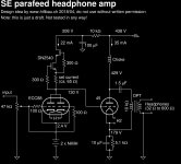
Ok, here's my draft for a headphone version.
I used a 10k load, which will still give plenty of power for headphones, but with better linearity. Brian Sowter confirmed that he could make a suitable transformer (similar to the Sowter 8665, but with a higher winding ratio). The 1.5 uF parafeed coupling cap with the 10k load will give a cut-off frequency of about 10 Hz.
For normal speakers, a 5k:8 transformer or so may be better to achieve higher power.
The ECC88 driver tube may not be very exciting, but it's quite linear and allows biasing the driver stage at a relatively low voltage, so the whole amp ends up at a B+ well below 500 VDC. And I have a bunch of good ECC88 tubes in the basement.
I kept the autobias for the 45 output stage because that will gracefully adjust the bias if the tube characteristics drift away from their textbook values.
Comments, suggestions, ideas?
Attachments
- Home
- Amplifiers
- Tubes / Valves
- 45 amp build direct coupled