Well it's dead horse beating time. I have too many parts including over a dozen 45's. I was going to build one of several amps but could never decide. John Tucker's parafeed direct coupled 45 has always stuck in my mind.
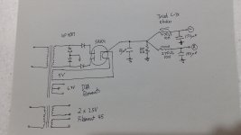
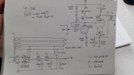
I have attached some photos of schematics I'm playing with. Many missing values. I am thinking of Lundahl iron but am open to suggestions and changes. Maybe I'm barking up the wrong tree.
I'll leave it open for comments.
I have attached some photos of schematics I'm playing with. Many missing values. I am thinking of Lundahl iron but am open to suggestions and changes. Maybe I'm barking up the wrong tree.
I'll leave it open for comments.
Attachments
Last edited:
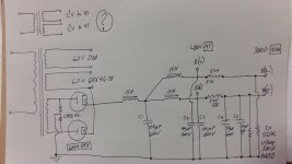
Ok...that is a messed up power supply and completely the wrong attachment. I will upload the correct one next
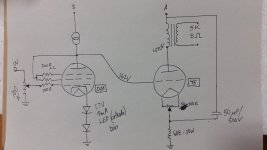
it will works fine i will make 3 change if it was mine , lundhal plate choke instead of CCS for the D3A , resistor and film cap for the D3A cathode bias ,
and film cap to ground for the 45 cathode. 😉
and film cap to ground for the 45 cathode. 😉
I would build the amp just about as you have it drawn. Since you need HLMP-6000 diodes for the C4S, just buy a few extras and settle for 1.57V of bias on the cathode of the D3A. I would not recommend a resistor and capacitor as a substitute for the LED, but it's certainly easy enough to try. It is worth mentioning that a plate choke on the driver can allow you to take driver B+ from the cathode of the 45.
I would absolutely go parallel feed if you possibly can. If you're using a 5K transformer, very few of them have sufficient inductance to give satisfying bass performance. I would look for at least 40H of primary inductance on your OT. With parallel feed, getting 100H isn't a problem.
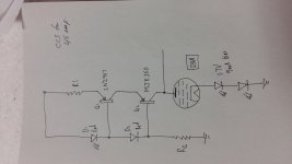
The MJE5731A should replace the MJE350 in your C4S load. The metal tabs face in opposite directions, but otherwise the 5731A will handle more voltage and is much easier to heatsink.
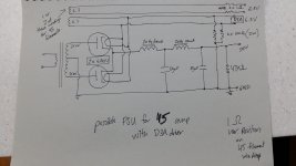
The note about "1 or 2 of these windings for 45 filaments" is concerning. Each 45 needs its own filament winding!
I would absolutely go parallel feed if you possibly can. If you're using a 5K transformer, very few of them have sufficient inductance to give satisfying bass performance. I would look for at least 40H of primary inductance on your OT. With parallel feed, getting 100H isn't a problem.
The MJE5731A should replace the MJE350 in your C4S load. The metal tabs face in opposite directions, but otherwise the 5731A will handle more voltage and is much easier to heatsink.
The note about "1 or 2 of these windings for 45 filaments" is concerning. Each 45 needs its own filament winding!
If you decide to do a Parafeed circuit, you will need a couple of things:
A very high quality air gapped plate load choke for the 45. It will need lots of Laminations, and lots of inductance.
A very high quality non-electrolytic high voltage capacitor to couple from the junction of the Plate and Plate Choke, to the Parafeed output transformer primary.
A 40H plate load choke(not nearly high enough inductance), and a 40H parafeed output transformer will have an effective load on the 45 of 20H. 20H is only 2,500 Ohms of inductive reactance.
A 100H plate choke and 40H parafeed output is 28.6H; it has 3,593 Ohms inductive reactance at 20Hz, that is a little better.
Of course depending on the capacitance of the Parafeed coupling cap, the Parafeed OT primary impedance, the music frequencies, and the loudspeaker load on the Parafeed output transformer, there will be large variations of impedance that the 45 is driving.
Sorry, I mixed up my recommendations a bit. With a 5K gapped transformer, inductance is a huge problem.
With parallel feed, a 40-50H plate choke is generally not hard to find for your application, and will work marvelously with a 4-5K output transformer.
With parallel feed, a 40-50H plate choke is generally not hard to find for your application, and will work marvelously with a 4-5K output transformer.
audiowize,
Yes, I forgot that the Parafeed transformer will probably have 100H to 300H or so.
That works with a 40H - 50H choke.
I keep putting off building a Parafeed amp, but you tempt me to order a pair of plate chokes.
Yes, I forgot that the Parafeed transformer will probably have 100H to 300H or so.
That works with a 40H - 50H choke.
I keep putting off building a Parafeed amp, but you tempt me to order a pair of plate chokes.
If you're using a 5K transformer, very few of them have sufficient inductance to give satisfying bass performance.
Then it is not a 5k transformer 😀🙄
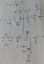
The 4.4K resistor needs to be a whole heck of a lot bigger than 10W, I would look for at least 20W. You also have two parallel feed caps. You can return the bottom of the primary of the output transformer to the top of the cathode bias resistor.
You swapped the Emitter and Collector connections in the updated schematic. The Collector needs to be connected to the plate of the tube.
And the transistor is a PNP, the arrow of the Emitter needs to point into the transistor.
You do not want the Emitter of a transistor to be the plate load for the input tube
(Emitters are low impedance).
And the transistor is a PNP, the arrow of the Emitter needs to point into the transistor.
You do not want the Emitter of a transistor to be the plate load for the input tube
(Emitters are low impedance).
Last edited:

How about battery (NiMH) bias instead of the LED bias?
NiMH cell has 1.2V, so two in series has too much voltage.
At 2.4V bias the D3a anode voltage rising over 210-215V, so the operating point moving to the -more- non-linear region and accessible swing is significantly decrease.
I just said NiMH because this type has the lowest dynamic resistance I believe. Other battery types may provide a better biasing voltage. But heck, the whole battery bias thing was just a wild idea that would be easy to try instead of the LEDs (I did in another amp, and I liked it). No big deal.
I would consider a gyrator load with non-inductive film resistor on the cathode (caddock). Also D3a could be replaced with other triode strapped pentodes.
E180F, E280F and 7788 should all be up to the task and are a little more obtainable these days.
E180F, E280F and 7788 should all be up to the task and are a little more obtainable these days.
Wow....800 views may indicate a group build. If possible I'd like to stick to a high mu driver, ccs, parafeed....optimizing the current amp with fewer major changes. Any help with values would be great. Brands of parts have not been settled. I'm not married to a particular smoothing cap. Bill Epstein described Obigato magic and insisted on tube rectification.
In short I'm not a designer. The schematic has already been a collaboration. Draw me the gyrator and let's see what others think but I was intending to stick closer to the original circuit.
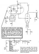
I have attached Tucker's drawing here
In short I'm not a designer. The schematic has already been a collaboration. Draw me the gyrator and let's see what others think but I was intending to stick closer to the original circuit.
I have attached Tucker's drawing here
Attachments
- Home
- Amplifiers
- Tubes / Valves
- 45 amp build direct coupled