SONY MFB Piezo Servo Update Pictoral
I'd like to try one of these SMD accelerometers on my set up but think it is going to be tough to beat the ole reliable piezo disk.
Next post is back of prototype open baffle speaker with sony woofers mounted, one with piezo - see previous posts.
The important thing is that you've cleared up any worries about whether these little piezo sensors can cope with the accelerations encountered by a woofer cone!
-Gnobuddy

I'd like to try one of these SMD accelerometers on my set up but think it is going to be tough to beat the ole reliable piezo disk.
Next post is back of prototype open baffle speaker with sony woofers mounted, one with piezo - see previous posts.
SONY MFB Piezo Servo Update Pictoral
Steph_tsf -
Thank you for the advice - I am still trying to understand it all.
As Gnobuddy admonished many months ago...there is a lot of stress involved with testing these prototypes, esp. when MFB phase is reversed - when one powers up..yikes! Please see above and below posts.
Agree 100%. Gnobuddy is right. Meanwhile, our friend hombre has not yet reported about instability, howling or oscillation. This is bizarre. Possibly hombre piezo MFB schematic is still defective.
Like Gnobuddy wrote, our friend hombre should build a piezo preamplifier breadboard featuring a proper low frequency compensation, featuring a selectable MFB phase reversal, featuring a lowpass filter defining the high frequency where the MFB gradually vanishes at F1 (say 1 kHz ?), and featuring a potentiometer allowing to vary the MFB signal amplitude, prior entering the mixer.
Like Gnobuddy wrote, our friend hombre should also build a mixer breadboard featuring the mixer (MFB signal merging with the audio input signal), featuring the loop amplifier (say a x10 wideband amplification), featuring some extra bass boost (say a x3 amplification at 30 Hz), and last but not least, featuring the required lowpass shelving filter that's in charge of resetting the loop amplification to x1 at F2 (say 1 kHz also ?) and all the above frequencies. The last bit being critical what's regarding stability.
Only in case the MFB application is a subwoofer, the above lowpass shelving filter can become a leaking integrator that's resetting the loop amplification to x1 at F2 (say 1 kHz also ?), and because of its integrating nature, that's also imposing a 6 dB attenuation at 2 kHz, 12 dB attenuation at 4 kHz, 18 dB attenuation at 8 kHz, 24 dB attenuation at 16 kHz, and so on. Progressively muting the high frequencies above F2 inside the action chain, improves the MFB stability margin.
Steph_tsf -
Thank you for the advice - I am still trying to understand it all.
As Gnobuddy admonished many months ago...there is a lot of stress involved with testing these prototypes, esp. when MFB phase is reversed - when one powers up..yikes! Please see above and below posts.
It seems to be a little SMD piezo sensor, specifically designed to measure acceleration. The datasheet specifies accelerations up to 50 G, while my back-of-the-envelope calculations suggest you need a few hundred G's - say 500G to be sure - for a woofer MFB sensor.
-Gnobuddy
Gnobuddy's post on this SMD prompted me to post an update on my Sony MFB project. In brief for those still interested, here is what I have done since last January?'s post.
Through a series of baby steps, working backwards from a defunct pair of Genesis subwoofers + I purchased several cheapo ($25) Chinese class D amp (actually turned out to be pretty decent!) to work with the genesis servo preamp circuit. I powered this class d amp from the +/- 53V of the sony amp power supply...totally lucked out on the voltage there. as it is near the max for the Class D amps
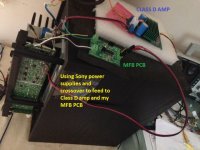
Then after several months...I figured out how to use some software to design pcb boards and started having them made in China. I started off with making the piezo->buffer -> integrator/low pass filter -> mixer. I was going to use the low pass filter from the sony sub to run into my circuit at the point of the mixer. I was going to try the Chinese Class D amp or maybe the Sony amp to power the sub with the servo circuit. After thousands of iterations, I may have something promising but I don't think I can use the sony preamp part feeding directly into my little servo PCB - it works okay with pure tones and with the woofer in the sony box (with port plugged) but with music in the open baffle I think some higher frequencies are getting through an distorting the sound - i.e. sounds worse with the servo (MFB piezo).
I thought I had it working Sony Preamp->my servo circuit->back into Sony Amp->to Sony woofer with piezo mounted (see attached pic) and + feedback sounded good...even in the Sony box.
I did my R&D with the woofer in the Sony box but when I translated to open baffle setup is when I ran into problem. I thought maybe low pass filter was not enough or phase shift wasn't compatible...I don't know so I purchased a cheap Chinese subwoofer crossover filter + the class D amp + power from sony power supply plus +/-14v power supply from sony to run my servo circuit, I have something that is functional.
The trickiest part it so mount the piezo with just the right amount of area over the fulcrum to get the right amount of bending to get the output to match what is needed for feedback in the circuit. A lot of this has finally come together in my mind the past few weeks so I am excited about the hope of getting something finalized.
Thanks to Gnobuddy, Bolserst, Steph_tsf, Bentoronto and others for all their input.
Attachments
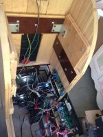
SONY MFB Piezo Servo Update Pictoral - Yikes!
Here is the rear of one of the open baffles with a pair of sony woofers mounted...Two Sony amps + various renditions of pcb boards (8 revisions at least!). this set up is a lot more complicated than what I was envisioning when I first started...LOL
One big disappointment...how noisy my cabinets are at moderate volumes :-( but seems to be diminished with servo (accelerometer plugged in (vs accelerometer not plugged in to PCB)
Attachments
Measurements?
Here's a measurement just for MF that anybody can do without a mic and get pretty sanitary results. First, do a REW sweep of the amp with a 10-Ohm resistor in place of the speaker. It should look pretty flat and clean.
Then do a sweep with the MF system running. The sweep should show a distinct drop in voltage at the system resonance (where it should be cutting power to the driver because that is what it should be doing) and also show 1% or more distortion (because it is sending a distorted signal to the speaker to undistort the sound).
Depending on the typology, the bass may sloping. That is also a sign the MF is working as it should. Obviously a simple matter to EQ to your taste (and there is no physically correct bass "house curve" other than the psychoacoutically right one for you).
If you do square waves, you might get some really dramatic pictures. In order to combat cone inertia, an MF system gives the driver a substantial "kick in the pants" to get it moving fast.
It has been reported a few times that dust caps just aren't solid enough and add junk to the accelerometer signal. Perhaps just well north of the sub-woofer region where most people want their MF to operate. Perhaps, as you say, yours is solid enough. The alternative - surgery on the dust cap - is nicely illustrated apropos phase plug implementations at the Planet 10 website. Still sounds scary to me.
B.
Last edited:
Thanks for the suggestion Ben. I may be able to try that test. I do not have ideal set up / space really for testing...and that I try to transpose what I find at the 'workspace' where the scope, power and OEM Sony box and woofer are to the cramped and precariously place boards, wires and open baffle system makes things a bit complicated. Right now, just using ears.
With open baffle set up, I occasionally get some large swings of the woofer say around 2-5 Hz on top of the music if I push things just a bit...I think it may be clipping..not of the amp but of the preamplifier but not sure.
Next I want to move the class D amp in place of the Sony amp but want to use the +/-53V of the sony power supply to power the class D and I dread taking the open baffle speakers apart to be able to get at the sony amps.
Hopefully more to come....
Gnobuddy's post on this SMD prompted me to post an update on my Sony MFB project. In brief for those still interested, here is what I have done since last January?'s post.
Through a series of baby steps, working backwards from a defunct pair of Genesis subwoofers + I purchased several cheapo ($25) Chinese class D amp (actually turned out to be pretty decent!) to work with the genesis servo preamp circuit. I powered this class d amp from the +/- 53V of the sony amp power supply...totally lucked out on the voltage there. as it is near the max for the Class D amps
Then after several months...I figured out how to use some software to design pcb boards and started having them made in China. I started off with making the piezo->buffer -> integrator/low pass filter -> mixer. I was going to use the low pass filter from the sony sub to run into my circuit at the point of the mixer. I was going to try the Chinese Class D amp or maybe the Sony amp to power the sub with the servo circuit. After thousands of iterations, I may have something promising but I don't think I can use the sony preamp part feeding directly into my little servo PCB - it works okay with pure tones and with the woofer in the sony box (with port plugged) but with music in the open baffle I think some higher frequencies are getting through an distorting the sound - i.e. sounds worse with the servo (MFB piezo).
I thought I had it working Sony Preamp->my servo circuit->back into Sony Amp->to Sony woofer with piezo mounted (see attached pic) and + feedback sounded good...even in the Sony box.
I did my R&D with the woofer in the Sony box but when I translated to open baffle setup is when I ran into problem. I thought maybe low pass filter was not enough or phase shift wasn't compatible...I don't know so I purchased a cheap Chinese subwoofer crossover filter + the class D amp + power from sony power supply plus +/-14v power supply from sony to run my servo circuit, I have something that is functional.
The trickiest part it so mount the piezo with just the right amount of area over the fulcrum to get the right amount of bending to get the output to match what is needed for feedback in the circuit. A lot of this has finally come together in my mind the past few weeks so I am excited about the hope of getting something finalized.
Thanks to Gnobuddy, Bolserst, Steph_tsf, Bentoronto and others for all their input.
Do you still have those Genesis subs? We would like to see their sensor construction!
Sorry if this has been posted somewhere in this thread but I have some basic questions.
Can MFB be used to 20khz? I understand the phase delay of the feedback limits the bandwidth of the MFB but can't you use laser sensors or some sort of phase corrector to compensate?
Can MFB be used to 20khz? I understand the phase delay of the feedback limits the bandwidth of the MFB but can't you use laser sensors or some sort of phase corrector to compensate?
In principle, yes and yes.Can MFB be used to 20khz? I understand the phase delay of the feedback limits the bandwidth of the MFB but can't you use laser sensors...
But unlike subs, many tweeter drivers are pretty clean and "fast" already. And, unlike the idiotic situation with subs, the resonant freqs of midrange drivers and tweeters are not within their passband*. So the need to use corrective feedback is less pressing.
Apropos high frequencies and laser position measurement, a feedback signal needs to compulsively and continually track the input signal within a reasonable few degrees of phase of the input signal... or else you get howlback and driver destruction. And the cleanliness of the feedback signal determines the cleanliness of the final sound. Can a laser device (or an accelerometer or an IPAL) meet those requirements?
B.
*it would seem to be a trivial extension of technology to manufacture sub speakers with sub-sonic resonance
Last edited:
I think I can pull it off but it will be very expensive and require lots of testing. What's the average distance a driver will displace itself at 20khz?Can a laser device (or an accelerometer or an IPAL) meet those requirements?
Hard to tell if that is a very sophisticated question or one suggesting innocence of basic electronic theory?What exactly causes the phase delay in the feedback?
But.... let's say you want to use a mic placed at 6 inches from a sub driver to provide feedback. At 50 Hz, your mic feedback would be a few degrees late. That's OK.
But when a midrange driver is playing at 500 Hz, you'd be a whopping 90 degrees late*.
B.
*no, you can't put a delay into the speaker signal because....
Last edited:
I've literally only designed zero feedback amps since I started learning electronic theory. My feedback understanding is garbage. I've been learning as needed.Hard to tell if that is a very sophisticated question or one suggesting innocence of basic electronic theory?
I don't understand how higher frequencies arrive at the input later than lower frequencies.
Can I assume the MFB medium is not to blame? I was thinking since laser sensors have 200khz bandwidth they could avoid this issue.
You are speaking of phase shift?I don't understand how higher frequencies arrive at the input later than lower frequencies.
They don't arrive later.I don't understand how higher frequencies arrive at the input later than lower frequencies.
The speed of sound (around 1130 feet per second) does not change with frequency, but higher frequencies have shorter wavelengths, each full wavelength comprising 360 degrees of phase, one rotation of the phase "compass wheel".
A 50 Hz wavelength is 22.6 feet long, 6 inches represents, as Ben says, "only a few degrees", actually 7.96 degrees, a few more than a few, but who's counting ;^).
Since a 500 Hz wavelength is only 2.26 feet (27.12 inches) long, 6" would represent 79.64 degrees, just 10.36 degrees shy of a "whopping 90 degrees".
That said, placing a mic 6 inches from a sub driver to provide feedback would be a poor choice from a signal to noise standpoint, -18 dB from one placed .75 inches away, about 9.95 degrees of phase at 500 Hz...
Last edited:
Okay I think I understand what you are saying. But a laser sensor should have effectively 0 delay since it is reading the vibration at the speed of light plus the bandwidth of the circuitry after it (200khz in this case). This would solve the issue right?
- Home
- Loudspeakers
- Subwoofers
- Commercial motional feedback woofer available sort of