Hi weltersys,
Art, "environmental influences" can be analysed and filtered in measuring (and correction) software, these days. For instance, room correction software like Dirac Live already implemented impulse response correction. In that sense IPAL wasn't as groundbreaking some hoped for...
Regards,
Djim
Art, "environmental influences" can be analysed and filtered in measuring (and correction) software, these days. For instance, room correction software like Dirac Live already implemented impulse response correction. In that sense IPAL wasn't as groundbreaking some hoped for...
Regards,
Djim
Exactly, and this is why we measure....1) They never are…
REW measures how a woofer actually responds to the input signals at the time of measurement, not how a manufacturer or some modeling program says it should….or how it behaved at a lower volume level 5 minutes earlier...or 6 months ago on a really cold day.
I had no intention of spending any time providing an example of old vs new measurement methods. Generally when somebody brings forward a claim to a time tested method or theory the burden of proof is on that somebody, not the rest of the community.
But…last weekend I was visiting an old friend who happens to still be using one of Bill Walso’s early measurement systems that could use both old(impulse) and new(MLS) test signals to measure loudspeakers. I must admit to a feeling of nostalgia as I heard the “tick tick tick” sounds coming from the vented bookshelf speaker under development. So, I asked if I could grab a few measurements of the near field response of the woofer using both methods with levels matched as best I could.
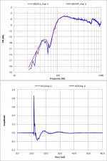
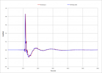
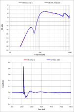
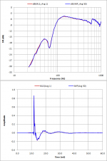
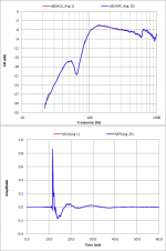
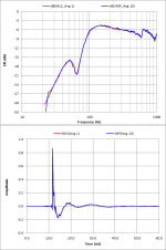
Here are the results with no smoothing or any other data manipulation:
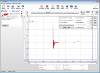
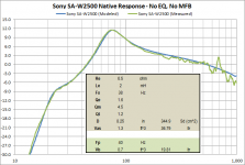
Attachment #1 thru #6: These are impulse and frequency response comparisons between a single MLS data capture(red curve) and 1, 5, 10, 25, & 100 impulses(blue curve). You can see that it only takes a few averages to clean up the majority of the HF noise, but LF noise remains a problem even with 100 impulses averaged...which takes the better part of 2 minutes to acquire. This is because all the HF information is contained in the first few mS while the LF information is spread out over the rest of the 50mS time window where there is much more opportunity for noise intrusion and the signal is of lower amplitude.
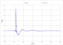
Attachment #7: A zoom in on the impulse comparison.
Attachment #8: A zoom in on the impulse comparison with curves shifted to more easily see that there aren’t any missing features in the MLS version of the impulse response.
For those who have no clue what I mean by “tick tick tick”, I have attached a cell phone capture of the impulse test in progress.
This is the sound of State-of-the-Art loudspeaker testing from the 80s.
Attachments
-
 IMP_Avg_001.png38.3 KB · Views: 414
 -
IMP_10x.zip152.3 KB · Views: 94
-
 IMP_Zoom_shift.png28.7 KB · Views: 134
 -
 IMP_Zoom.png26.4 KB · Views: 115
 -
 IMP_Avg_100.png35.3 KB · Views: 127
 -
 IMP_Avg_050.png35.7 KB · Views: 388
 -
 IMP_Avg_025.png35.6 KB · Views: 389
 -
 IMP_Avg_010.png36.2 KB · Views: 402
 -
 IMP_Avg_005.png36.5 KB · Views: 406
Last edited:
If there's a chance that I understand Bolserst's traces, it establishes that collecting audio data by sweeps or by impulses are about as perfect as anyone could want since they exactly duplicate one another.
I gather that one method uses an impulse stimulus and the other a frequency sweep. The impulse method can produce a freq response almost perfectly duplicating the sweep method's sweep curve and the sweep method can produce an impulse profile almost perfectly duplicating the impulse method's impulse trace.
Since I am used to seeing nothing but messy real-world data when I collect it*, it looks to me like a great achievement to match that precisely for both methods - and even in just a single run of each.
Do I have that right?
(Of course, I may never understand why REW shows the impulse starting before zero time?)
Ben
*OK, when I simply repeat a freq response with REW a few seconds apart, I am astonished how perfectly the two runs match. But if I move the mic an inch, messy!
Ben,If there's a chance that I understand Bolserst's traces, it establishes that collecting audio data by sweeps or by impulses are about as perfect as anyone could want since they exactly duplicate one another...The impulse method can produce a freq response almost perfectly duplicating the sweep method's sweep curve and the sweep method can produce an impulse profile almost perfectly duplicating the impulse method's impulse trace.
Since I am used to seeing nothing but messy real-world data when I collect it*, it looks to me like a great achievement to match that precisely for both methods - and even in just a single run of each.
Do I have that right?
*OK, when I simply repeat a freq response with REW a few seconds apart, I am astonished how perfectly the two runs match. But if I move the mic an inch, messy!
Messy!
OK. Bolserst's "traces" are presumably at a similar, probably low voltage level.
The concept of correction of low to high level differential is presumably what you pursue in this thread, as any decent sub can work near perfect at one watt or so.
Since you have purported a multiplicity of subs to be preferential, which obviously will have a differential output, why do you pursue motional feedback?
Cheers,
Art
It’s probably not that important, but it still sounds like you are under the impression that the sweep method determines a frequency response and then from that the impulse response is calculated. That would be how a gated sinewave method works to determine the impulse response, but not the swept sine method. As described in post#698, the swept sine wave directly determines the impulse response by convolution with the reversed time signal. Then, from the impulse response, the frequency response can be calculated.…I gather that one method uses an impulse stimulus and the other a frequency sweep. The impulse method can produce a freq response almost perfectly duplicating the sweep method's sweep curve and the sweep method can produce an impulse profile almost perfectly duplicating the impulse method's impulse trace…
It’s actually rather fascinating to me how similar the impulse and swept sine signals are to each other. Both contain all frequencies at the same magnitude. The only difference is that the impulse signal has all frequencies at the same phase, and the swept sine has phase varied with frequency. The convolution with the reversed time signal “reverses” the phase warping, lining all the phases back up to get the impulse. Wiki has a nice animation showing that about 2/3rd the way down the page here:
https://en.wikipedia.org/wiki/Chirp
For convenience, I attached the animated gif below.
The DSP book I mentioned also has some information on this type of signal and a brief description of why it was/is important for radar and sonar due to its improvement in S/N ratio while retaining the time resolution of the returned impulse. Chirp Signals
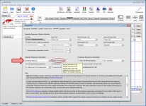
Probably because you have selected option to align peak of impulse at time zero. This results in removing all delay from the phase response.Of course, I may never understand why REW shows the impulse starting before zero time?
Check on the “Analysis” tab of the “Preferences” window…don’t forget to scroll thru the help menu at the bottom of the window for details on the options.
If you are interested in quantifying and retaining the “time of flight” in your measurements, the easiest way is by using the other channel of your measurement system as a loop back timing reference. Then when you take measurements you will see the impulse offset in time consistent with the mic distance from the acoustic source. REW even calculates this distance for you and gives you many options in the controls sub-window to manipulate or remove this delay. Depending on the version of REW you are using you may also have the option to select the timing reference from the measurement window right before performing the sweep. Of course with time of flight included, the plotted phase response will "wrap up" at higher frequencies due to the delay.
Attachments
Last edited:
Many thanks once again. A conscientious reader needs time to digest it all.
And back to your post #698 that you mention, I think there may still be ugly differences between the well-behaved results for electronic filters versus drivers in ported boxes, even if it sort of aspires to be like a 4th order filter.
So, the post #702 comparison is between a Dirac instantaneous pulse versus a chirp (rather than between a Dirac pulse and a slow sweep)? Still impressive to see the match, even if not quite the same chasm that would be if a slow sweep was compared to an impulse.
Thanks for help with REW time alignment settings.
Ben
Not quite sure what this has to do with measurement methods. Remember, REW does not know what type of enclosure you are working on or whether the woofer has a cardboard or aluminum cone…it just measures it. If the measured response for a vented enclosure matches a 4th order filter response as a simple lumped parameter model would predict, great. If it doesn’t, that is fine too. This just tells you that the way you built the enclosure there are some parts of the system that are not behaving like a simple lumped mass or lumped compliance...nothing "ugly" about it. Usually in this case the differences are a result of pipe/waveguide type behavior between the driver/enclosure/port which can be modeled but is more difficult to do, or nonlinear behavior in an undersized port which is difficult if not impossible to model. In general, as long as the box is not too elongated and the port not undersized the lumped model provides very good approximation of the acoustic behavior of the system. You may recall that the lumped model for the vented enclosure that is the subject of this thread matched measured results very well, especially considering how unconventional the box/tuning alignment was. (Post#211) I'd previously never seen a vented enclosure like it.… I think there may still be ugly differences between the well-behaved results for electronic filters versus drivers in ported boxes, even if it sort of aspires to be like a 4th order filter.
The post#702 compared measured impulse/frequency response between Dirac type pulse stimulus and about 3 seconds of MLS stimulus with levels set just below clipping level for sending the pulse thru a 100W/8ohm power amp.So, the post #702 comparison is between a Dirac instantaneous pulse versus a chirp (rather than between a Dirac pulse and a slow sweep)? Still impressive to see the match, even if not quite the same chasm that would be if a slow sweep was compared to an impulse.
Long or short sweep, the impulse recovery process in the same. In case you weren't aware, you can select the length of the sweep by choosing the number of data points to acquire in the REW measurement window. The sample rate you have selected in the REW preferences window will also affect the length of the sweep (lower sample rate = longer sweep for the same number of data points). When measuring speakers I tend to use sweep lengths on the order of 3 seconds…a nice compromise between resolution, S/N, and minimizing risk of contamination by outside noise sources. When measuring rooms, longer sweeps are advantageous to improve low frequency S/N.
Attachments
When I read your careful defences of modelling, I think of Voltaire's Dr. Pangloss ("we live in the best possible of all worlds"). Granted, your evidence is unassailable, as always.... This just tells you that the way you built the enclosure there are some parts of the system that are not behaving like a simple lumped mass or lumped compliance...nothing "ugly" about it. Usually in this case the differences are a result of pipe/waveguide type behavior between the driver/enclosure/port which can be modeled but is more difficult to do, or nonlinear behavior in an undersized port which is difficult if not impossible to model...
But part of our difference in opinion has to do with those final few iotas of difference. It isn't so much that the model has to look pretty close to the measured results to the eye as that the match has to be close enough that the small differences aren't obvious to the ear as audible distortion.
In turn, that might relate to the critique of the famous Edward Tufte ("The Visual Display of Quantitative Information"). When you present the curves with an axis in dBs, a few perhaps very audible percent are imperceptible to the eye.
Sorry to post so abstractly. Wish I had some data instead.
Ben
Last edited:
Ben
A designer needs to understand the extent to which he can rely on his models. Everyone understands that they are not perfect. (Read "Models Behaving Badly" for what happens when people put too much faith in their models.) Use the models to get you as close to your design goals as you can and then tweak the final design using good measurements. To my knowledge that's pretty much the way all good loudspeaker designers work. (Although some seem to ignore measurements altogether!)
A designer needs to understand the extent to which he can rely on his models. Everyone understands that they are not perfect. (Read "Models Behaving Badly" for what happens when people put too much faith in their models.) Use the models to get you as close to your design goals as you can and then tweak the final design using good measurements. To my knowledge that's pretty much the way all good loudspeaker designers work. (Although some seem to ignore measurements altogether!)
Has anybody this century suggested loudspeakers are controlled by unpredictable malicious spirits rather than physics models?*
There are two themes in recent posts:
1. Can EQ to a speaker make it behave just like the electric-equivalent model? For example, is "undoing" the principal resonance with EQ the same as motional feedback?
2. My big quandary, what are the best ways to test/demonstrate, and/or measure the results of MF? And inherent in that question, how to present that information in the most meaningful way? For example, if MF's main benefit is controlling cone overshoot** to transient inputs (which means taming the impulse response), how to illustrate it?
Ben
*OK, maybe some of the time its the spirits in action
**actually, the often mentioned glory of MF is in counter-acting initial undershoot to an impulse and thereby making subs seem "faster" and with a whole lot more impact; I suppose controlling overshoot makes a speaker seem "tighter"; both "tighter" and "faster" are nice properties
Last edited:
- Can EQ to a speaker make it behave just like the electric-equivalent model? For example, is "undoing" the principal resonance with EQ the same as motional feedback?
- My big quandary, what are the best ways to test/demonstrate, and/or measure the results of MF? And inherent in that question, how to present that information in the most meaningful way? For example, if MF's main benefit is controlling cone overshoot** to transient inputs (which means taming the impulse response), how to illustrate it?
- As far as I understand that's what the folks over at klippel are trying to accomplish - digitize a driver response, compare it to the source and use DSP to flatten things out which basically is a static feedforward system. Like what nokia was researching before they got eaten by Microsoft. MF is different in a way that it's a dynamic feedback system able to take things like VC temp and position in the loop, feedforward systems traditionally require strict manufacturing tolerances to perform well. Have yet to hear it perform better then an accelerometer based mf system.
- Good Q, in other words how do I sell MFB without having customers onsite to convince them 😛 I think you would need a drDre like product manager to do that, let me know if you find one 😎
looks like we're brothers in crime 🙂__________________
HiFi aspirations since 1957. Currently working on motional feedback again... the final frontier in audio
Last edited:
- As far as I understand that's what the folks over at klippel are trying to accomplish - digitize a driver response...
in other words how do I sell MFB without having customers onsite to convince them...
Thanks for great post. Agree, big difference between the enterprise of Klippel and the empirical viewpoint of feedback.
As my math teacher used to say, with enough variables you can draw an elephant and move its trunk. But once the elephant starts moving? Just as it is good to model say magnet poles, good to model the whole darn thing. That can lead to better designed drivers and maybe pre-corrected DSP amps. But seems to me a kind of engineer's fantasy that starts with something that "must" be true in theory but might not make sense in practice.
Feedback, by contrast, doesn't need to model the device, just establish that the usual criteria (like gain and phase) are met in the loop. Glad to have a "brother in crime". Seems inevitable that feedback in the largest imaginable loop is a good thing.
My interests are not commercial. Like the famous words of Lord Kelvin, if you can't measure it, you are just whizzing in the breeze. Measures need to be technically sound but they also need to communicate the message well to others.
I hope everyone will look at your Piratelogic website link in your post.*
Ben
*Ummm, pity they weigh so much or somebody could make a smartphone app that uses a retired smartphone as a speaker accelerometer.
Last edited:
Like the famous words of Lord Kelvin, if you can't measure it, you are just whizzing in the breeze. Measures need to be technically sound but they also need to communicate the message well to others.
The StarBass dev is done in close coöperation with the folks over at mfblabs.nl where lots of interesting mfb sensor R&D can be found and where the StarBass IV proto measurements will also be made available. Mfblabs is a non commercial site run by Hans Mons, the former Philips mfb dev lead. Its forum requires registration and is mostly in the dutch language but english posts are accepted as well.
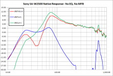
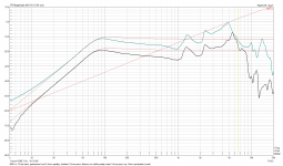
Attached a sample fr graph of a paddo accelerometer done by René over at mfblabs.
Attachments
Last edited:
Thanks again.Attached a sample fr graph of a paddo accelerometer done by René over at mfblabs.
That is an impressive graph. Its shows (I am guessing here) the accelerometer output matches some criterion output across the band that matters in MF (that is, the range of piston motion).
Good as it looks, that may be too gross a demonstration.
I wonder if the requirement for an accelerometer is to achieve a level of accuracy like the THD that is itself a fraction of the speaker THD. As is conventional in feedback thinking, the character of the feedback becomes the nature of the loop.
Ben
Yup, the accelerometer response should mimic the driver's sonic output as close as possible.Its shows (I am guessing here) the accelerometer output matches some criterion output across the band that matters in MF (that is, the range of piston motion).
I was poking around on the Mouser website recently, and stumbled across these: http://ca.mouser.com/ProductDetail/...=sGAEpiMZZMvEGZ0tfWSvRyT5DvGB1ckdnfpM9PRXAj0=
It seems to be a little SMD piezo sensor, specifically designed to measure acceleration. The datasheet specifies accelerations up to 50 G, while my back-of-the-envelope calculations suggest you need a few hundred G's - say 500G to be sure - for a woofer MFB sensor.
Still, as far as I can tell from the datasheet, it's a passive sensor, no internal electronics to overload, so it's quite possible that it will actually work at 500G.
It's also light, cheap, and small, so if it continues to produce a good acceleration signal at a few hundred G's of acceleration, it may turn out to be a good MFB sensor.
Capacitance is only 0.77 nF, so it will take a charge amplifier with something like a 22M feedback resistor in order to get flat response down to 10 Hz or so.
Dunno about Mouser, but Digikey also has a number of piezo "bender" discs, some of them small enough to have acceptably high first resonance frequencies, in the range of several kHz.
-Gnobuddy
It seems to be a little SMD piezo sensor, specifically designed to measure acceleration. The datasheet specifies accelerations up to 50 G, while my back-of-the-envelope calculations suggest you need a few hundred G's - say 500G to be sure - for a woofer MFB sensor.
which datasheet are you referring to ? this one mentions a shockresistance of 1500G...
Weird, I can't find the one I was looking at earlier. It was several pages long, and looked as though it was quickly typed up by an engineer, rather than carefully designed by graphics professionals, like the one you linked.which datasheet are you referring to ? this one mentions a shockresistance of 1500G...
No matter. The important thing is that you've cleared up any worries about whether these little piezo sensors can cope with the accelerations encountered by a woofer cone!

-Gnobuddy
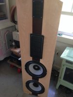
SONY MFB Piezo Servo Update Pictoral
It has been a while since I have posted on DIYaudio but thought I would give a brief update of my progress on attempting to use a piezo disk mounted to Sony woofer + circuit to buffer, integrate and mix with preamp signal.
Taking woofers out of original box and putting in another larger open box - not my best work but using scraps and a hand saw and a miter saw just to get shape roughed in.
more pics and posts below......
I wonder if the requirement for an accelerometer is to achieve a level of accuracy like the THD that is itself a fraction of the speaker THD. As is conventional in feedback thinking, the character of the feedback becomes the nature of the loop.
Ben
It has been a while since I have posted on DIYaudio but thought I would give a brief update of my progress on attempting to use a piezo disk mounted to Sony woofer + circuit to buffer, integrate and mix with preamp signal.
Taking woofers out of original box and putting in another larger open box - not my best work but using scraps and a hand saw and a miter saw just to get shape roughed in.
more pics and posts below......
Attachments
SONY MFB Piezo Servo Update Pictoral 2
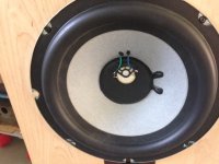
Close up of Sony woofer with piezo attached to dust cover.
Some may cringe at the though of me mounting the piezo this way, but base on my intuition and feel (the dust cover is flat and thick and does not flex with this little weight on plus my mounting hardware surface is large and spread out over a large area. Sine wave outputs look real good.
Attachments
- Home
- Loudspeakers
- Subwoofers
- Commercial motional feedback woofer available sort of