Rpsrrp and Rpsrrn are switches:
During test of PSRR you need to disable input signals! Cut the trace from "V4" to "Vin".
- value 1T = switch open
- value 1n = switch closed
"PWRGRND" is not viewable on picture - is it low ohmic connected to ground?
BR, Toni
Hi Sir Toni,
Yes the low ohm resistor is attached I just copied the whole scheme. Is it OK to omit these "switches" they don't look to have reference in my schematic. Do I have to connect the input to ground then?
Regards,
Albert
Hi Sir Toni,
Yes the low ohm resistor is attached I just copied the whole scheme. Is it OK to omit these "switches" they don't look to have reference in my schematic. Do I have to connect the input to ground then?
Regards,
Albert
You need those switches because VPSRR as a 1V sinus source is added between 50V power source and V+ from amplifier.
Input needs to be grounded during this test.
BR, Toni
using the protection values in post1 E2You can examine those error currents (stealing base currents from drivers) using the simulation.
The limiter transistors need to be biased relatively high so always some leakage currents flow. A slow down capacitor (22pF) is already installed. IMHO if you make it too big you have 2 problems which increase also THD:
higher nonlinear capacitance from driver base to emitter via current limiter diode and current limiter transistor/resistor divider.
too slow reaction on high current transients on short circuit
If you install the amplifier directly at/in the speaker box you can avoid the use of a current limiter which I would prefer.
In post # 2174 I have measured the THD+N20k@60W@8R with 0.0018% when VAS diode and current limiter are not installed. So one can decide himself which level of protection to use ...
you have ~433mVbe on the protection transistor.
That is already turning on the protection transistor even when there is no output current flowing to the load.
Some of the protection values are shown as optional, I have left them open circuit.
680r1 || 1300r = 446r5
39k+12k = 51k
Vsupply = 50V (ignoring the 15Vz)
Vbe = 50V * 446.5 / (51k+446.5) = 433mVbe
That value needs to be reduced below 400mV and maybe below 350mv to reduce the effects of it starting to turn on.
The 22pF looks like a stability value.
What about adding a 10uF, or 1uF, or 100nF, across the 1k3?
Did you look at that, to attenuate the triggering on fast short duration peak output currents?
I have the amp operating without any output protection at the moment, so I have not tried to investigate how it limits during excessive output.
My "rule for limiters" is:
All valid output signals must pass to all valid loadings.
For a 100W into 8ohms capable amplifier that would imply outputs of 40Vpk and >15Apk
That means the protection transistors must not be starting to turn on when those valid signals and loads are occuring.
Post 1 E2 is SA2016 lateral mosfet - not the currently measured SA2015 IXYS v-mosfet? 😕using the protection values in post1 E2
you have ~433mVbe on the protection transistor.
...
Sorry for OT,
Dave I'm trying to send you message about IXYS MOS models, but you have full storage of your "messagebox". Could you send me this models as private message?
Thanks!
Dave I'm trying to send you message about IXYS MOS models, but you have full storage of your "messagebox". Could you send me this models as private message?
Thanks!
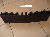
it will help equalise the heatsink backplate temperatures. But not much because the thermal goop is not squeezed down to metal to metal contact.
I can't see how you could bolt these together.
the best would be a very thick cover plate between the two above and below the active devices. But even that will have significant thermal resistance.
I can't see how you could bolt these together.
the best would be a very thick cover plate between the two above and below the active devices. But even that will have significant thermal resistance.
This way.it will help equalise the heatsink backplate temperatures. But not much because the thermal goop is not squeezed down to metal to metal contact.
I can't see how you could bolt these together.
the best would be a very thick cover plate between the two above and below the active devices. But even that will have significant thermal resistance.
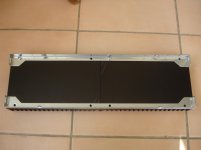
It is a part of dissipante3U from Modushop.https://www.modushop.biz/site/index.php?route=product/product&path=66_96_105&product_id=208
Attachments
Last edited:
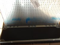
That does even less. Can you calculate the thermal resistance of that small area steel coupling?
No i can't.That does even less. Can you calculate the thermal resistance of that small area steel coupling?
That does even less. Can you calculate the thermal resistance of that small area steel coupling?
It's so high it is not worth trying.No i can't.
Dear Timios,
you may need a heatspreader. Operating the amplifier modules at about 450mA total bias dissipates 38W per side.
The modu heatsinks have 0.5 K/W for your 200x40x120mm sized heatsink parts. So the temperature rise above ambient will be minimum 19 degree. If you don't like up to 60 degree hot heatsinks in summer you can ask a local supplier for 2 pieces 200x80x6mm aluminium parts to build your own heatspreader.
(Will have a look into bin if I can find some suitable parts ... will send you an email soon.)
BR, Toni
Thanks Toni but i'm afraid that i can't find 6mm aluminium in Greece.Dear Timios,
you may need a heatspreader. Operating the amplifier modules at about 450mA total bias dissipates 38W per side.
The modu heatsinks have 0.5 K/W for your 200x40x120mm sized heatsink parts. So the temperature rise above ambient will be minimum 19 degree. If you don't like up to 60 degree hot heatsinks in summer you can ask a local supplier for 2 pieces 200x80x6mm aluminium parts to build your own heatspreader.
(Will have a look into bin if I can find some suitable parts ... will send you an email soon.)
BR, Toni
My previous attempt was unsuccessful.
Sorry,i know this is off topic but i want your opinion.
Is it a good solution some thermal paste applied between two pieces of heatsink in dissipante 3U?
Hi Thimios,
I encountered the same, what I actually did is clip them together by a sturdy stainless steel clip. [top & bottom] DIY because I can't find one in the local hardware shop. AndrewT is correct joining them together with a bolt is a tough job. Apply a small amount of thermal grease because when you clip them the pressure will push the grease out.[provided the corner edges are perfectly flat] When you mount the output trannies make sure to evenly space them. For example, for 4 pairs 2 trannies on the left and 2 on the right making the joined edges at the center position of the 4 outputs. That is if you plan to mount the output trannies directly to the heatsink, same applies if you will be using angular aluminum bar [L shape].
Sa muli,
Albert
- Home
- Amplifiers
- Solid State
- 2stageEF high performance class AB power amp / 200W8R / 400W4R