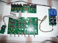
Today I finally powered up and listened to this competend preamplifier.Easy to build ,works perfectly,without hum,buzz or other weird noises.I noticed only one thing,in comparison to another pre,much simpler in design(a pot folowed by an op amp):noise at full volume with no signal was louder(with the ear sticked to the speaker,otherwise the difference wasn't noticesble).I listened to FM stations,through a pair of Visaton B80's.Sound was likeable,without flaws,as far as I can tell.Anyhow,the strong advantage of this pre is the tone control,which is very versatile.My compliments to Douglas Self and Carl Huff!
Attachments
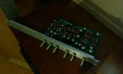
That's good to hear. I have nearly finished my construction. Been working on the chassis today, using a 1U rack mount case
I wish you full success.I also intend to use an 1U chassis,but the one I found locally,according to the dealer's statement,has double bottom plate and somewhat lower internal height than 35mm,which is the minimum,in order to fit the selector pcb.I am interested to read about your progress in the construction.
Thank you. I had a few problems with a couple of errors in the BOM. My PCB is the v1.3, very similar to yours, there was I minor mistake on the component layout printed on it, but thankfully I spotted it. Hopefully there aren't any I haven't spotted! Also I've used omeg eco pots which required slight pin bending to fit. I shall try to upload a picture, I haven't done it before so, we shall see..........or not 😀
Attachments
Electrolytics
Why are NON Polar electrolytics specified for Polar electrolytic locations ?
Have the Circuit locations been verified for Level of DC Bias on the NON Polar devices ?
The price is virtually 3X for NO reason ?
Levels of DC Bias on NP capacitors is a No..No ?
Why are NON Polar electrolytics specified for Polar electrolytic locations ?
Have the Circuit locations been verified for Level of DC Bias on the NON Polar devices ?
The price is virtually 3X for NO reason ?
Levels of DC Bias on NP capacitors is a No..No ?
Why are NON Polar electrolytics specified for Polar electrolytic locations ?
Have the Circuit locations been verified for Level of DC Bias on the NON Polar devices ?
The price is virtually 3X for NO reason ?
Levels of DC Bias on NP capacitors is a No..No ?
In the original article the only non-polar electrolytics were the two at each input, to cope with unpredictable fault voltages from outside. Do you have more?
In the original article the only non-polar electrolytics were the two at each input, to cope with unpredictable fault voltages from outside. Do you have more?
Doug,
Nice to see you here.
As described in the BOM, those caps that are not film are specified as 35v Nichicon MUSE 'green caps'.
those caps
Carl I think Douglas would like to know which caps 'those' are. Are there any more except the two input caps? Link to that BOM you mentioned?
Jan
All the electrolytics in the BOM are nichicon muse es (non polar)
The implication I got from ArtM's post is that that is a problem?
The implication I got from ArtM's post is that that is a problem?
Carl I think Douglas would like to know which caps 'those' are. Are there any more except the two input caps? Link to that BOM you mentioned?
Jan
Here is the BOM. For the most part, the BOM has not changed from the prototype. www.dropbox.com/s/crfkdsh9ukmq3pi/DSELF_PREAMP_BOM_01.xls
The part numbers relate to the schematic that I provide. Since it is based upon IP crafted by others I have been slow to publicly post it.
Nichicon MUSE 'green caps' are well respected in the signal path.

Last edited:
Here is the BOM. For the most part, the BOM has not changed from the prototype. The part numbers relate to the schematic that I provide. Since it is based upon IP crafted by other I have been slow to publicly post it.
Nichicon MUSE 'green caps' are well respected in the signal path.
I think the BOM got stuck on the internet highway - nowhere to be seen 😉
And Carl, no offense intended, but, really, I hope you do not base your judgement of these caps on some ad copy ...
Jan
I think the BOM got stuck on the internet highway - nowhere to be seen 😉
And Carl, no offense intended, but, really, I hope you do not base your judgement of these caps on some ad copy ...
Jan
I fixed the BOM URL. No offense taken by your comment. Nichicon MUSE is a 15 year favorite of mine. Others agree with me. For example pop the cover off of a $20K Theta Casablanca. There are so many green caps inside it looks a small garden lawn!
Jan, do you have an equivalent preference for electrolytic caps?
So to (finally!) being able to answer Doug's question: there are a bunch of electrolytics on this BOM in addition to the input coupling caps. I don't have the schematic this BOM is extracted from, sorry. Maybe someone can post it so we actually know what we are talking about.
No specific brand favorite; I normally look at the datasheets for the ones that fit the voltage/value spec, maybe size as well, and lowest price, depending on use, for things like temp range, leakage, DA. But I use very little electrolytics in audio. Only in power supplies of course, but in a good design these are anyway out of the equation.
Jan
Am I the only one who's a bit confused by this conversation??
Sorry for not answering you directly. There is no reason not use the NICHICON MUSE parts specified in the BOM. They are 'Bi-Polarized' and designed for use in audio signal paths.
Since Jan requested, here is the schematic that the BOM references ...
https://www.dropbox.com/s/urc16peyg23iqge/DSelf_Schematic_01.pdf?dl=0 and https://www.dropbox.com/s/mfxxpf58qggms0e/DSelf_Schematic_02.pdf?dl=0
Thanks Carl. It just all seemed like a bit of an odd conversation since that post by Art M, anyway, that's nothing new on diyaudio! 😀
The schematic shows Non Polarized Electrolytics for Only the Input and Output coupling as stated by D Self.
The BOM for V13 board shows Non Polarized Electrolytics for virtually All locations (16).
My fault for not reconciling the Schematic with the Suggested BOM before ordering.
Not real clear from Reading the Bates article as to what is optimum ( Bias V.S distortion).
The BOM for V13 board shows Non Polarized Electrolytics for virtually All locations (16).
My fault for not reconciling the Schematic with the Suggested BOM before ordering.
Not real clear from Reading the Bates article as to what is optimum ( Bias V.S distortion).
... Not real clear from Reading the Bates article as to what is optimum ( Bias V.S distortion).
Art if you build the preamplifier as specified I am certain you will be very happy with the results.
I invite the several happy builders on this forum to add their comments.
Art if you build the preamplifier as specified I am certain you will be very happy with the results.
I invite the several happy builders on this forum to add their comments.
I am sure you are right Carl. I don't intend on making Negative comments about the Project. It makes for an interesting exchange in discussing Circuit and Component aspects. Thanks for all your work.
- Home
- Source & Line
- Analog Line Level
- Doug Self Preamp from Linear Audio #5