This is a good safety measure for painted and/or anodised cases.popchops, as you have the same case as i do, what ive done is to connect the earth from the mains input to the rear panel.
Then from the rear panel (same connection point) i've taken an earth coloured cable (yellow with green line) and connected it to the bottom plate.
From my two SMPS's i then connected individually from their earth connection to the bottom plate, using only one connection point.
It ensures that a stray mains wire touching the floor will blow the mains fuse, rather than leaving the panel LIVE waiting for you or your family to touch it.
The Chassis to Main Audio Ground (MAG) is a Safety connection. It is NOT required for audio. It should not make the audio any better nor any worse. But it does. I find that adding the Chassis to MAG safety connection NEVER makes the audio performance better. Often it makes the performance worse. Excess noise/interferences.Do I need a ground loop breaker on each PS connection (filter cap output) to the chassis?
I guess my bigger question is: should I treat the 1mm steel baseplate as a 'star' node and connect everything to it (albeit at different locations)? Thx, Pops.
Sometimes the solution is to adopt a Disconnecting Network (DN) instead of a direct wire safety connection.
Ask your self:
Do I have two separate and isolated channels inside my chassis?
Then you NEED two separate Chassis to MAG safety connections. Each MAG must have the Safety connection to ensure that any exposed conductive parts (RCA/Phono sockets) are not LIVE in the event of a mains failure incident.
If however the two, or more, channels share a common MAG, then you would only need ONE MAG to Chassis Safety connection.
The Safety connection MUST survive longer than it takes a mains fuse to rupture and the arc to extinguish.
A bigger fuse than is necessary will extend very significantly how long it takes for the fuse to rupture.
Use a close rated fuse if at all possible.
Is that a 2kW SMPS?Each SMPS already has a 10 amp fuse on the live input.
10A mains fuse will pass 20A for many seconds. That on a 220Vac supply amounts to ~4400W being dissipated across the fault. How hot will that get if the fuse takes 30 seconds to rupture?
Last edited:
the output should ONLY have the NFB connected. There must be no other load.
NFB ?
Negative FeedBack
PE, now NFB, have you done any research before starting work on mains powered projects?
Your life and your projects are in your hands.
PE, now NFB, have you done any research before starting work on mains powered projects?
Your life and your projects are in your hands.
Last edited:
Is that a 2kW SMPS?
10A mains fuse will pass 20A for many seconds. That on a 220Vac supply amounts to ~4400W being dissipated across the fault. How hot will that get if the fuse takes 30 seconds to rupture?
Surely you should know the answer to your own questions!
You having built the Q-Watt and fitted the SMPS, should know!
Last edited:
I know nothing about your SMPS.
And don't us the title "professor".
I am not and never claimed to be.
And don't us the title "professor".
I am not and never claimed to be.
If you have selected well matched emitter resistors, then you will find that the voltages also match.
If have 2pair then the sum of the upper exactly equals the sum of the lower.
The differencebetween the upper resistors is an indication of how well you have selected your matched pair. Similarly the lower resistor voltages indicate the selection quality of your lower pair.
Again, read the schematics and you'll find that the Q-Watt uses only one pair (one NPN and PNP each) of - rather beefy - output devices. Astonishingly, though 🙄.
Best regards!
and from that it followsAgain, read the schematics and you'll find that the Q-Watt uses only one pair (one NPN and PNP each) of - rather beefy - output devices. Astonishingly, though 🙄.
Best regards!
If anyone reads this and thinks, "but I used two pairs".If you have selected well matched emitter resistors, then you will find that the voltages also match.
then the next addresses how to assess their arrangement.
I am trying help, not trying to be difficult.
Is that a 2kW SMPS?
10A mains fuse will pass 20A for many seconds. That on a 220Vac supply amounts to ~4400W being dissipated across the fault. How hot will that get if the fuse takes 30 seconds to rupture?
It is apparently usual to fuse SMPS lots more than really needed. For upcoming amp projects (Honey Badgers, Klein & Hummel clones, maybe Q-Watts...) I bought 24 pc. of really cheap open frame SMPS units, each one rated at 24V/2.5A. That calculates to 60 watts of DC output power. They all have 3.15A fuses at their inputs. Most probably these big values are needed dur to the very low impedance of the mains grid and the current surge on powering on.
Best regards!
I'll try to explain why they have to do that.
I have not dismantled many Mains SMPS but I find they all use an NTC to limit start up current.
They all do not use a bypass after the start up event is complete.
As a result they all need to use an NTC that does not severely limit the source impedance and adopt an NTC that allows a high start up current to charge the mains capacitors.
take your example of 60W of DC power and assume an overall efficiency of 90% (many are much better).
The input power is thus 66W. That is an average input current of 287mAac @ 230Vac
A close rated fuse for that would be T315mA or T500mA
But that would need an NTC of ~ 365ohms to 230ohms. This would also need a bypass that cut in as soon as the mains capacitors have charged up, i.e. in ~200ms to 500ms.
They don't do that because the big NTC and the delayed bypass would make their SMPS too expensive to manufacture and they would never sell many.
Instead they fit a 30 to 50ohms NTC and have to fit a big fuse to allow a high current start up. It is cheaper to make.
Leaving the NTC in place also reduces the input voltage at the mains capacitors.
An inherent limitation of mains SMPS is that as input voltage drops the input current increases to maintain constant power output.
This can be a big problem. It leads to overheating of the isolating transformer because high primary current is demanded to maintain the output voltage. It is better for reliability and performance if the source impedance is low. But that requires the NTC to be bypassed after it has completed it's start up current limiting.
Last edited:
This thread was solely about the Elektor Q-Watt amplifier is certainly going down the wrong path!
My Q-Watt as of 16th March 2017
Nice build!
Hint: you shouldn't mount the power transistors using such long cables. It is very likely that your amplifier starts oscillation in the HF range.
BR, Toni
Grounding
Hi All, - (esp. Calpe because you have the same case)
I have a quick question 🙂 on grounding the case walls and heatsinks... Is my existing steel bracket sufficient, joining the anodised walls (heatsink) to anodised backplate, to guarantee electrical continuity (see photo)? Should I sand off the surface coating underneath the steel bracket?
What is the best method for grounding the walls of the case? Do I need to drill more holes for direct wire connection? Doesn't seem logical since I already have holes with direct steel connection. Please help. I want to finalise my holy heatsinks.
Thanks - Popchops.
Attachments

Last edited:
Hi popchops, I too have some small issues too, but with my SMPS and the UK standard earth and grounds.
My time availibility is my lunch break, so of course my Q-Watts has been going on for far too long.
Your sure to get numerous opinions from people in the forum, but we both have the same case.
As you've probably seen from my posts I have a mains input socket (kettle type)
From the earth pin of this socket I have an earth cable (green/yellow) and it's connected to the rear panel, soldered to an earthing washer (with solder tab) on the fixing screw of the socket.
From the same earthing washer I have connected another earth cable (green/yellow) direct to the bottom plate, again using nut/screw and an earthing washer.
So might say don't rely on fixings scews, but 'our' case is very well built, so for me the case screws (and you know how well built the case is) is ample enough. I'm not having earth cables running around everywhere giving the appearance of spaghetti junction!
Any queries you know where I am or send me a personal message.
Calpe
Hi All, - (esp. Calpe because you have the same case)
I have a quick question 🙂 on grounding the case walls and heatsinks... Is my existing steel bracket sufficient, joining the anodised walls (heatsink) to anodised backplate, to guarantee electrical continuity (see photo)? Should I sand off the surface coating underneath the steel bracket?
What is the best method for grounding the walls of the case? Do I need to drill more holes for direct wire connection? Doesn't seem logical since I already have holes with direct steel connection. Please help. I want to finalise my holy heatsinks.
Thanks - Popchops.
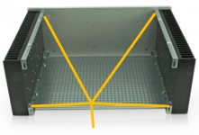
In practice you'll need to connect each panel to PE by means of a wire. The screws inside the enclosure are not good enough for that. This is important for safety reasons: the electric current will always choose the easiest way back to earth. For this reason you cannot trust “the enclosure connections”. Instead run a green / yellow wire from the PE at the input to each panel in the enclosure. You can use a star topology just like you do with GND.
EDIT: found an image of your enclosure to demonstrate what I would do in terms of PE wiring:
Attachments
Last edited:
A screw/bolt into a metal panel is good for a mechanical Earthed fixing.
Panels that are individually insulated by paint, or anodise, do rely on some other electrical connection. A screw into a tapped hole can be this connection.
I have not seen tapped holes that are anodised down the threads.
Panels that are individually insulated by paint, or anodise, do rely on some other electrical connection. A screw into a tapped hole can be this connection.
I have not seen tapped holes that are anodised down the threads.
Thanks delange for your valuable views, as I have the same case as popchops I'll follow your steps with the UK standard earth connections using a green/yellow cable.
Soldering cables to these earthing washers (with solder tab) on the fixing screwscrew as indicated by delange.
Soldering cables to these earthing washers (with solder tab) on the fixing screwscrew as indicated by delange.
- Home
- Amplifiers
- Chip Amps
- My Q-Watt project