Hi System7. Thank you for your post, your help is appreciated.
but, I can't understand what the point of your discussion is (my fault).
You are suggesting 4th order crossover for both drivers with also zobel network for correcting the impedence. Is it right?
I have simulated your crossover and this is the result with dibirama's files:
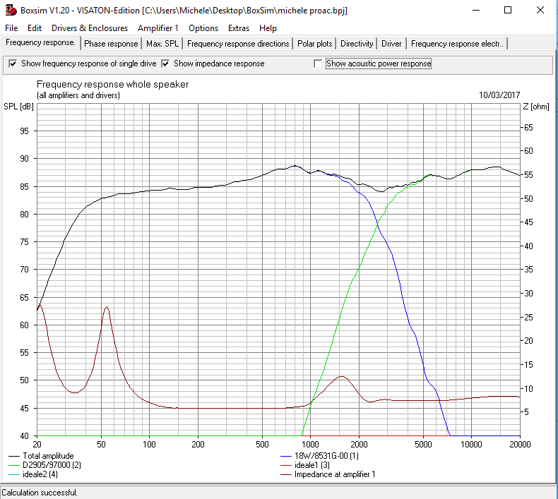
here we are. No baffle step compensation. This is why I can't understand what you wanna say 🙂
but, I can't understand what the point of your discussion is (my fault).
You are suggesting 4th order crossover for both drivers with also zobel network for correcting the impedence. Is it right?
I have simulated your crossover and this is the result with dibirama's files:
here we are. No baffle step compensation. This is why I can't understand what you wanna say 🙂
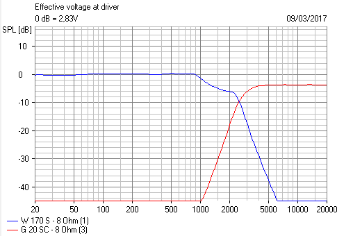
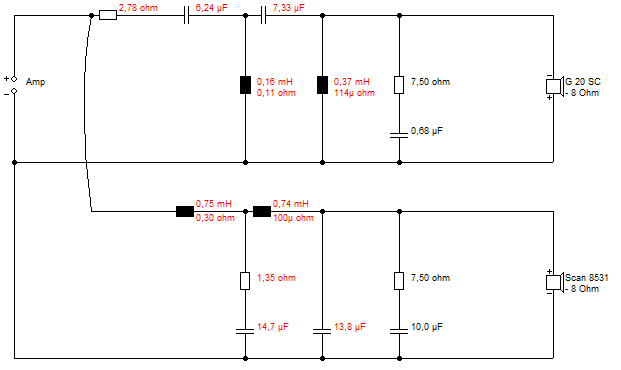
I'm actually not very bothered what the tweeter is, but used a 88dB G20SC to match yours. The woofer is a scanspeak 8531, because I used your ZMA and FRD files with a bit of fudging. The response seems to match the scanspeak data anyway. Time alignment was a bit guesstimate with your files. I could be wildly wrong on that. 😱
The theory says, once you get a LR4 curve on one driver, you just have to adjust the other driver filter for a matching LR4 result. And 4th order filters totally dominate individual tweeter response. The circuit is just what Boxsim optimiser came up with. It needs tidying up, but the 1.35R is a very critical component that works best when bigger IMO, because the impedance bump is ugly.
Hi Steve,
Woofer and tweeter in opposite phase ??
With your filter the woofer is filtered too much for high frequencies in a way there is too much phase lag in the woofer system and it becomes non minimum phase. So you have to set the tweeter in opposite phase to make the overall SPL again flat. The combined acoustical and electrical response should stay minimum phase. Your woofer will become too slow now, because its phase is lagging. This is not what the theory of LR4 is saying.
Last edited:
It wasn't my intention to suggest a filter. Just that 4th order seems to solve the problems here. I was scratching my head why there was no bafflestep:
And the polarity is a bit weird. I fixed the polarity with a bit of slope adjustment. Because I think this one is not quite LR4. But I did mention the problems I had with guessing time alignment.
But it seems to me that second order, even with a 5kHz tank notch, is just not giving enough control of all the lumps and bumps in the 8531.
I've always thought a 6" is the speaker from hell. Worst time alignment and not enough natural rolloff.
The ideas I am playing with here are some of Troels' stepped baffles:
18W-8434G00
SBAcoustics-61-NRXC
Or flat baffle with some cleverness:
Illuminator-Monitor
Mainly 4th order bass, you see. Some wriggle room with tweeter filter.
The bafflestep fiasco may be due to files I used being made on infinite baffle:
http://www.diyaudio.com/forums/multi-way/99926-scan-speak-crossover-help-23.html#post5013595
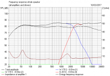
Adjusting for that gives cucicu's result, below. So far, so good, IMO. Something is working. 🙂
And the polarity is a bit weird. I fixed the polarity with a bit of slope adjustment. Because I think this one is not quite LR4. But I did mention the problems I had with guessing time alignment.
But it seems to me that second order, even with a 5kHz tank notch, is just not giving enough control of all the lumps and bumps in the 8531.
I've always thought a 6" is the speaker from hell. Worst time alignment and not enough natural rolloff.
The ideas I am playing with here are some of Troels' stepped baffles:
18W-8434G00
SBAcoustics-61-NRXC
Or flat baffle with some cleverness:
Illuminator-Monitor
Mainly 4th order bass, you see. Some wriggle room with tweeter filter.
The bafflestep fiasco may be due to files I used being made on infinite baffle:
http://www.diyaudio.com/forums/multi-way/99926-scan-speak-crossover-help-23.html#post5013595
Adjusting for that gives cucicu's result, below. So far, so good, IMO. Something is working. 🙂
Attachments
Hi Paul,
let me do some considerations at this point.
I think that at this point is unuseful trying more simulations because I understood that what appears on the simulator is very different from reality.
I don't know why it happens. Mybe the drivers, mybe the software, maybe the room, maybe myself 🙂.
What I also understood is taht these drivers don't sound good (to my taste) when arranged in a flat configuration. I think it is because of the paperish nature of this excellent woofer and because of the unregular response of both drivers on my square baffle.
I also have to remark how precious has been your job here, and wanna thank you once more.
So said, I have also to say that I'm in love with ProAc sound. I made a clone of response 2.5 many months ago, but using the same drivers of the original Proac the sound was horrible. So I made a completely new xover for that and the result was amazing to me and to my friends.
At this time, I see the basis for realizing a "simil ProAc" sounding speaker. I know it can appear absurde and no-sense, but for me, it has a lot of sense. I could go out and buy an original Proac, but it is not stimulating to me. I love DiY and I like difficulties in realizing a crossover. So in these days I'm having a good time with you on the forum. Wanna make the final satisfaction??? 🙂
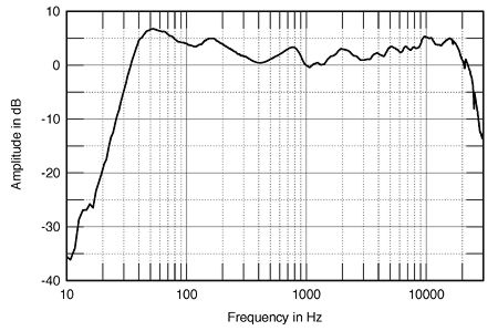
So said, I tried to "copy" the proac 2.5 FR on simulation, and trying to compare the sound of my actual with a couple of original proac of a friend of mine.
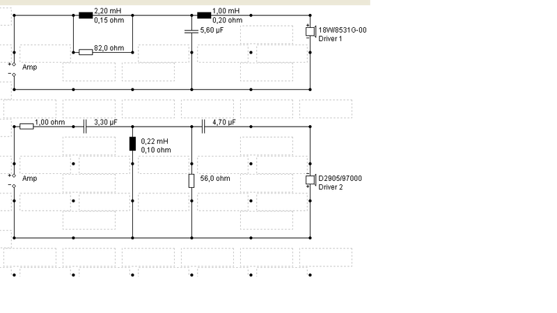
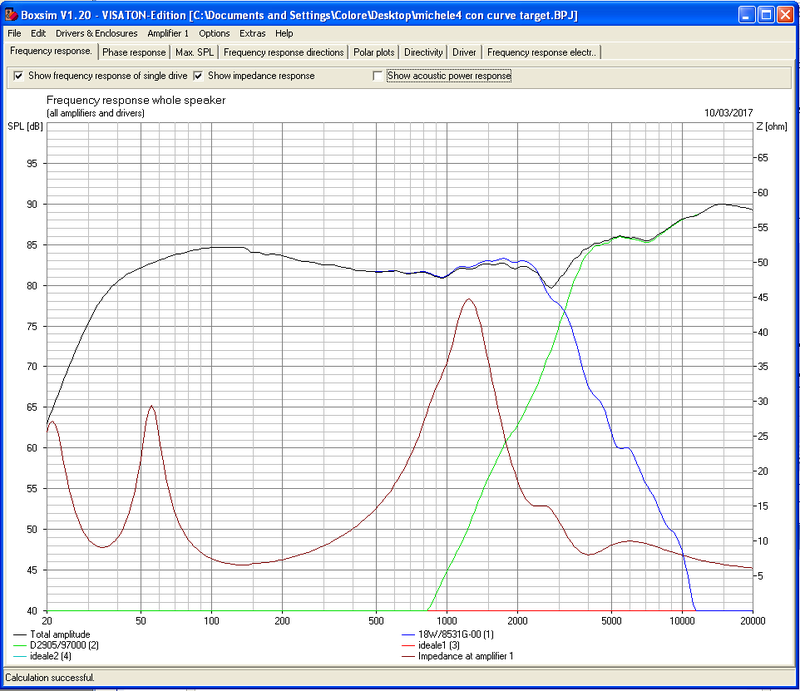
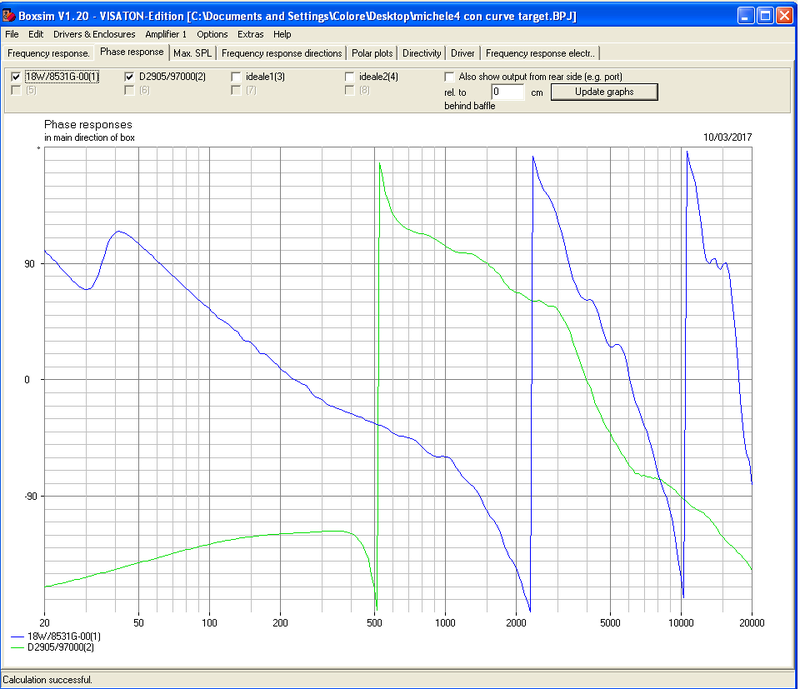
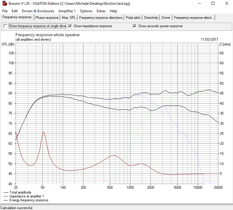
Well, I think I reached a perfect result with this crossover. Surely it will need some minor adjustements, but essentially i am very satisified. Let me share it with you. Could you simulate this, Paul and try to explain something about phase of this simulation? I can't understand how it is, if good or bad, but connecting the driver with the same phase, spl drops very very much.
NOTE THAT THE TWEETER IS REVERSE POLARITY.
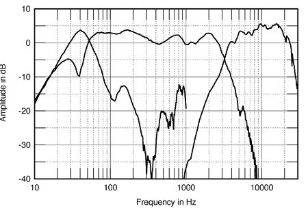
and this is proac 2.5 FR:
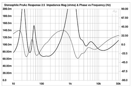
and impedance (please compare the impedances of mine and of the original and see how much similar they are):
let me know what do you think.
regards
let me do some considerations at this point.
I think that at this point is unuseful trying more simulations because I understood that what appears on the simulator is very different from reality.
I don't know why it happens. Mybe the drivers, mybe the software, maybe the room, maybe myself 🙂.
What I also understood is taht these drivers don't sound good (to my taste) when arranged in a flat configuration. I think it is because of the paperish nature of this excellent woofer and because of the unregular response of both drivers on my square baffle.
I also have to remark how precious has been your job here, and wanna thank you once more.
So said, I have also to say that I'm in love with ProAc sound. I made a clone of response 2.5 many months ago, but using the same drivers of the original Proac the sound was horrible. So I made a completely new xover for that and the result was amazing to me and to my friends.
At this time, I see the basis for realizing a "simil ProAc" sounding speaker. I know it can appear absurde and no-sense, but for me, it has a lot of sense. I could go out and buy an original Proac, but it is not stimulating to me. I love DiY and I like difficulties in realizing a crossover. So in these days I'm having a good time with you on the forum. Wanna make the final satisfaction??? 🙂
So said, I tried to "copy" the proac 2.5 FR on simulation, and trying to compare the sound of my actual with a couple of original proac of a friend of mine.
Well, I think I reached a perfect result with this crossover. Surely it will need some minor adjustements, but essentially i am very satisified. Let me share it with you. Could you simulate this, Paul and try to explain something about phase of this simulation? I can't understand how it is, if good or bad, but connecting the driver with the same phase, spl drops very very much.
NOTE THAT THE TWEETER IS REVERSE POLARITY.
and this is proac 2.5 FR:
and impedance (please compare the impedances of mine and of the original and see how much similar they are):
let me know what do you think.
regards
I think I should duck out at this point and let you guys continue. 🙂
Just an interesting quote from Troels to part with:

Do you detect, as I do, that Troels got deeply fed up with this speaker? 😀
Just an interesting quote from Troels to part with:
Illuminator-MonitorNot since the unfortunate 2.5 clone had I heard such low bass from a 6" driver, and this coming from a meager 21 liter. Quite impressive although you should not expect a full-bodied sound like a Jenzen speaker, which were in place when these were taken to the living room.
Do you detect, as I do, that Troels got deeply fed up with this speaker? 😀
Steve, the more feedback the better, that is just the power of a forum. Everybody has its idea about a good speaker design and a good sound. IMO you can always learn of it.I think I should duck out at this point and let you guys continue. 🙂
System7 I think you should stop writing here. The only thing here is that you are a Troels follower. You continue to propose his designs and simulations with completely different drivers from mine. Don't understand why and what you wanna demonstrate. The forum is for people, maybe you are at a such high level that I can't understand tour posts. So please, let the guys play and spend your time in a better way.
Cucicu,
I look to your Proac design this evening. I have to leave now.
Concerning DIY, in the case you should install some equipment, think about a IEC baffle at home. I have installed a 225Hz one. In that way you can measure your own infinite baffle responses. After some calibration and measuring TSP very accurate, it is possible. Look on my website, then you see how I have done it. The advantage is, once you have these infinite baffle curves of your own drivers, you can compare them with the curves you measure later on in enclosure. In that way you are able to analyse the baffle response yourself. It gives a lot of understanding.
When you like to do DIY you should do IEC driver measurement / making driver infinite baffle models / simulation drivers in enclosure and do measurement check/ X-over design / listen and tweak. That is how I do it for the moment and it is a pleasure doing DIY speaker design like that. That is my opinion about it.
Paul
After many proofs this afternoon I can conclude that the issue is the mid of the 18w.
It has a lot of bump and it is impossible to compensate.
I have here new inductor 1mh, 2.2mh, 2.7mh, 1.8mh, 0.47mh...i ask you if you can elaborate a flat baffle step response , the issue is there. Maybe your initial leap files were right. If i solve this, i can finish the project. The bump is indomable alse with 3rd order 2.7mh/cap/1mh.
Paul
The bump is indomable alse with 3rd order 2.7mh/cap/1mh.
I don't understand this English Cucicu, please write in other words because it seems important.
Can you give the serial resistances of your coils?
I have simulated your Procah design. My results are the same. Around 3200Hz it has a LR4 behaviour. But placing the woofer 20mm behind, the phase of the woofer is lagging more and an opposite phase for the tweeter gives a more flat SPL. I don't like the tweeter boost but when it sounds good, what can we say... Maybe your tweeter has a lower level, we don't know now.
Schematic filter 24 Procah

SPL filter 24 Procah and LR4 3200 targets

Phase filter 24 Procah @ woofer 20mm behind tweeter

LR4 target in grey
I will design a flat SPL filter with the Leap curves. Maybe crossover around 2800Hz? In that way you don't use the tweeter in the 1500-2000Hz region where the diffraction of the baffle is high, with a different SPL off axis as a consequence.
For a good understanding, you find the Procah not good enough because of the mid tones?
Last edited:
Sorry.
I wanna say that I can't manage the bump also with large inductors in a 3rd order configuration and using large coils (2.7mh -cap to ground-1mh).
Proac design looked good at the beginning cause the high level of the tweeter (i used only 1ohm damping) maybe masked the midrange bump but listening to some music like strings it is a too forward design.
Reset all, Paul: the issuw is not the baffle step. I just read that this woofer has a resonance on 800hz , as you can see drom rh datasheet. There is a small peak on impedance in 800hz ( that i measured).
So I think we should work to remove that peak, maybe with an RC zobel (also with B3 xover or LR4) or with a series notch filtere. This is defiitively the issue. Not yhe baffle step bur that resonance which gives midy sound.
Hi Cucicu
This is a B3 2750Hz. I have designed with the dibirama frd's and also with the Leap woofer frd to compare.
There is a serial notch on 800Hz. You can tune yourself by changing R of notch or increasing L and decreasing C to lower Q. You can do yourself in Boxsim.
SPL is optimal for woofer 10mm behind. For 20mm behind there is more boost on crossover point because drivers become more in phase.
I have looked for optimal power response and smooth electrical transfers.
When this is still bad I think you have to do a measurement. It still stays designing in the dark now, there is no reference.
Schematic filter25 B3 2750Hz

SPL filter25 B3 2750Hz dibirama fred's

SPL filter25 B3 2750Hz leap woofer frd and dibirama tweeter frd

Electrical transfer filter25 B3 2750Hz

Power filter25 B3 2750Hz

To change the tweeter level change both R1 and R4 to keep the same load on the filter.
-2dB : R1 = 5.1E and R4 = 4.3E
+2dB: R1 = 3.9E and R4 = 12E
This is a B3 2750Hz. I have designed with the dibirama frd's and also with the Leap woofer frd to compare.
There is a serial notch on 800Hz. You can tune yourself by changing R of notch or increasing L and decreasing C to lower Q. You can do yourself in Boxsim.
SPL is optimal for woofer 10mm behind. For 20mm behind there is more boost on crossover point because drivers become more in phase.
I have looked for optimal power response and smooth electrical transfers.
When this is still bad I think you have to do a measurement. It still stays designing in the dark now, there is no reference.
Schematic filter25 B3 2750Hz
SPL filter25 B3 2750Hz dibirama fred's
SPL filter25 B3 2750Hz leap woofer frd and dibirama tweeter frd
Electrical transfer filter25 B3 2750Hz
Power filter25 B3 2750Hz
To change the tweeter level change both R1 and R4 to keep the same load on the filter.
-2dB : R1 = 5.1E and R4 = 4.3E
+2dB: R1 = 3.9E and R4 = 12E
Last edited:
Hi Paul.
I just build your filter and it is very good. Notch filter is well spotted.
I made a FFT measurement (the best that I get) and Pink noise Third octave smoothed and I notice there is a bump on 300-400hz but also on the 1khz-2khz region.
I think that these can be the issues. Leaving out the 300Hz bump for the moment, I think definitively that the "midy" sound is given by the 1-2khz region. It is also evident from the simulation. Do you think that we can drop down that region of about 2db's?
here is your simulation, look at 1-2khz region
here is fft
I bring c15 of your schematics from 5.6 to 15uf and now the woofer is perfect. I will not touch it anyway.
I am pretty sure we have an issue with this damn tweeter.
It sounds midy, it screams in the lower treble.
If can help, many designers like sonus faber use this tweeter but they parallel a resistor at the inductor. In the guarneri evo there is a 15.6ohm resistor parallel to the inductor to ground of tweeter.
Maybe an issue of scanspeak tweeter when cut quite low. Also proac on the d2010-8513 puts a 47ohm resistor in that place. What do you think?
The rising response is a consequence of the notch at 800Hz, you see on the electrical response of the woofer. I try another way, maybe more flat below 1000Hz.
Very good to see your FFT, there is a reasonable good matching with the simulation. It gives more trust in this way. Do you apply "average on" in your FFT, you have to do.
I dont't believe so much in parallel resistors with coils, that they are needed. Indeed it lowers the Q, but more important is to realize the correct shape for the tweeter and when this will be done by the parallel resistor, no problem. But not a must to do IMO.
The peak at 300Hz can be a room resonance, but I am not sure. Now the SPL is also rising to low frequencies, maybe that is also an issue. I will simulate now and think about it further.
Yes i set average on. I can choose an average between 1 and 100 where 1 is "istantaneous" and 100 is slow in capturing.
I m changing way of working. I noticed , measuring only the woofer, that the pricky frequency is about 1.2khz and 1.6khz. I can hear it clearily also during the sweep. These are certainly the fastidious and too midy frequencies. So i suggest that notch at 800hz is not needed. It is better ( regarding the issue on 1.2khz and 1.6khz) at measurements and also to my ears a simple 2.7mh/12uf.
Better is 2.7mh/12uf-4.7ohm to ground/0.47mh.
In this way i measured and listened the the 1.2khz and 1.6khz become more attenuated and not pricky anymore.
So i will try with your help (please ) to sew a tweeter curve on this
I think, because the tweeter tends to sound forward, to make a ripid penndance, like b3 for the tweeter. The overlapping under the crossing point is terrible abd must be avoided. I say this after listening. This tweeter sounds bad when cut too low. Too energy in the 2khz region.
I am thinking in almost same way. Indeed no notch but in other way. And tweeter a little lower and a resistor to lower the Q.
I will send you also a flat SPL design with Leap woofer frd to try out.
Schematic filter26 B3 2750

SPL filter26 B3 2750 dibirama

I will send you also a flat SPL design with Leap woofer frd to try out.
Schematic filter26 B3 2750
SPL filter26 B3 2750 dibirama
Cucicu, here the design with Leap woofer frd and dibirama tweeter frd.
I also need then 2.7mH to make it flat, your favourite coil at this moment 🙂.
There is more mid filtering for the woofer. Response is between B3 and LR4 on crossover point now.
Schematic filter27 B3 2750

SPL filter274 B3 2750 Leap woofer and dibirama tweeter

I also need then 2.7mH to make it flat, your favourite coil at this moment 🙂.
There is more mid filtering for the woofer. Response is between B3 and LR4 on crossover point now.
Schematic filter27 B3 2750
SPL filter274 B3 2750 Leap woofer and dibirama tweeter

- Home
- Loudspeakers
- Multi-Way
- Scan-Speak crossover help